A Lesson In RF Design Thanks To This Homebrew LNA

If you’re planning on working satellites or doing any sort of RF work where the signal lives down in the dirt, you’re going to need a low-noise amplifier. That’s typically not a problem, as the market is littered with dozens of cheap options that can be delivered in a day or two — you just pay your money and get to work. But is there a case to be made for rolling your own LNA?

[Salil, aka Nuclearrambo] thinks so, and he did a nice job showing us how it’s done. The first step, as always, is to define your specs, which for [Salil] were pretty modest: a low noise figure, moderate gain, and good linearity. He also wanted a bandpass filter for the 2-meter amateur radio band and for weather satellite downlinks, and a bias-tee to power the LNA over the coax feedline. The blog post has a detailed discussion of the electrical design, plus some good tips on PCB design for RF applications. We also found the discussion on bias-tee design helpful, especially for anyone who has ever struggled with the idea that RF and DC can get along together on a single piece of coax. Part 2 concentrates on testing the LNA, mostly using hobbyist-grade test gear like the NanoVNA and tiny SA spectrum analyzer. [Salil]’s tests showed the LNA lived up to the design specs and more, making it more than ready to put to work with an RTL-SDR.

Was this more work than buying an LNA? Absolutely, and probably with the same results. But then again, what’s to learn by just getting a pre-built module in the mail?

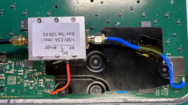
A bias tee module added inside the Starlink terminal, connected to the pads where a GPS antenna used to be wired

GPS Antenna Mods Make Starlink Terminal Immune To Jammers

The Starlink receivers need positioning and precise timing information to function, and currently the best way to get that information is to use a global navigation satellite system (GNSS) such as GPS. Unfortunately, the antenna used for this secondary satellite connection leaves something to be desired. Of course, when it comes to solving Starlink problems, there’s no one best than [Oleg Kutkov], whose duty is to fix and improve upon Starlink terminals used in Ukraine — and when the specific problem is GPS bands getting jammed by the invading military, you better believe that a fix is due.

[Oleg] sets the scene, walking us through the evolution of GPS circuitry on the Starlink terminals. Then he shows us the simplest mods you can do, like soldering an improved passive antenna in place of the chip antenna currently being used. Then, he takes it up a notch, and shows us how you could attach an active antenna by using a bias tee module, a mod that would surely work wonders on more than just this device! Then, he brings out the test result tables — and the differences are impressive, in that the Starlink terminals with active antenna mods were able to get GPS signal in areas with active jamming going on, while the unmodified ones could not.

The post is exceptionally accessible, and a must read for anyone wondering about GPS antenna reception problems in customer-accessible devices. This is not the only Starlink hardware mod we’ve seen [Oleg] make, we’ve just covered his Starlink Ethernet port restoration journey that meticulously fixes Ethernet connectivity oversights in the newer models, and the blog also has an article about powering Starlink terminals without the need for PoE, so, do check it out if you’re looking for more!

Everything You Didn’t Know You Were Missing About Bias Tees

Do you need a bias tee? If you want to put a DC voltage on top of an RF signal, chances are that you do. But what exactly are bias tees, and how do they work?

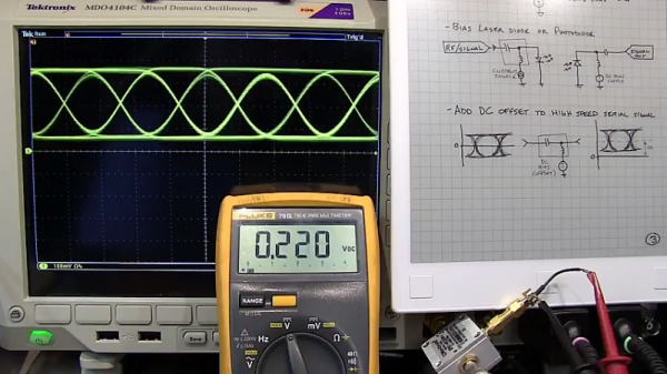
If that’s your question, [W2AEW] has an answer for you with this informative video on the basics of bias tees. A bias tee allows a DC bias to be laid over an RF signal, and while that sounds like a simple job, theory and practice often deviate in the RF world. The simplest bias tee would have a capacitor in series with the RF input and output to pass AC but block DC from getting out the input, and a DC input with a series inductance to prevent RF from getting into the DC circuit. Practical circuits are slightly more complicated, and [W2AEW] covers all you need to know about how real-world bias tees are engineered. He also gives some use cases for bias tees, from sending DC signals up a feed line to control an antenna tuner or rotator to adding a DC bias to a high-speed serial line.

It’s an interesting circuit, and we learned a lot, which is par for the course with [W2AEW]’s videos. Check out some of his other offerings, like a practical guide to the mysteries of Smith charts, or his visualization of how standing waves work.

Continue reading “Everything You Didn’t Know You Were Missing About Bias Tees”