We all know that Google and other big players pick and choose what information people see, but we sometimes overlook it outside of the search and social media space. [Lauren Leek] decided to take a look at how Google Maps picks winners and losers in the restaurant scene in London.
Building a machine learning model to determine a new restaurant recommendation (as one does), [Leek] uncovered interesting, and perhaps concerning, elements of how Google Maps ranks restaurants. Broken down by relevance, proximity, and prominence, many new restaurants face the issue of not drawing traffic without reviews and vice-versa causing a vicious cycle. Relevance and proximity are fairly straightforward, but what goes into “prominence?”
[Leek] found that “it is not just what people think of a place – it is how often people interact with it, talk about it, and already recognise it.” This leads to chains and high foot traffic areas awash in reviews while more out-of-the-way places find it more difficult to draw traffic. Some of this is expected and would be happening even when word of mouth was the primary way to find out where to eat, but as with many things, the algorithm amplifies this, along with the undisclosed paid placement of restaurants in Maps results.
While still in its infancy, [Leek] built a public dashboard where people can sort restaurants in the city. The machine learning algorithm is designed to identify places that are hidden gems that punch above their Google Maps weight and may make you look like the trendy one (if you live in London).
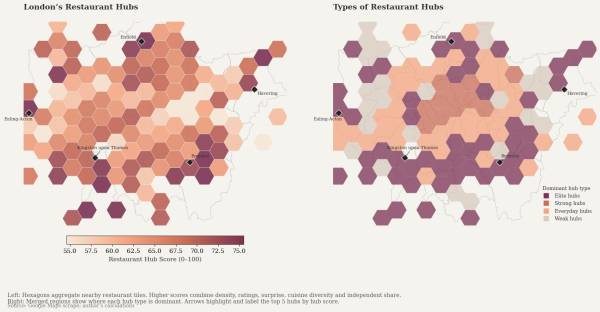
Zooming out further, [Leek] found larger clusters that revealed restaurant “diversity, in other words, is not just about taste. It is about where families settled, which high streets remained affordable long enough for a second generation to open businesses, and which parts of the city experienced displacement before culinary ecosystems could mature.”
If you want to step outside the algorithm mayhem, how about a good old-fashioned Web Ring? We’ve also addressed what’s an AI versus an algorithm, and Cory Doctorow advised us on how to reverse course on the current wave of enshittification.