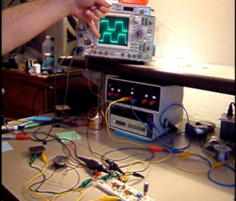
Before there were samplers, romplers, Skrillex, FM synths, and all the other sounds that don’t fit into the trailer for the new Blade Runner movie, electronic music was simple. Voltage controlled oscillators, voltage controlled filters, and CV keyboards ruled the roost. We’ve gone over a lot of voltage controlled synths, but [Tommy] took it to the next level. He designed a small, minimum viable synth based around the VCO in an old 4046 PLL chip
For anyone who remembers [Elliot]’s Logic Noise series here on Hackaday, this type of circuit should be very familiar. The only thing in this synth is a few buttons, a variable resistor for each button, and the very popular VCO for an analog square wave synth.
The circuit for this synth is built in two halves. The biggest, and what probably took the most time designing, is the key bed. This is a one-octave keyboard that’s completely 3D printed. We’ve seen something like this before in one of the projects from the SupplyFrame Design Lab residents, though while that keyboard worked it was necessary for [Tim], the creator of that project, to find a company that could make custom key beds for him.
The rest of the circuit is just a piece of perf board and the 4046. This project is all wrapped up in a beautiful all-wood enclosure with 3D printed hinges, knobs, and a speaker grille. The sound is phenomenal, and exactly what you want from a tiny monophonic square wave synth. You can check out a video of that below.


