
We’ve all seen these sensors and modules kicking around, as part of beginner kits, strapped into prototypes and potentially even in products deployed in the field. Yet as [John Teel] rightfully points out in a recent video, most of these have no business ever being used in a real product, and might not even be suitable for prototyping.
First up is a combination of the related DHT11 and DHT22 temperature-humidity sensors. As common as these are, they’re also pretty sketchy with their proprietary one-wire protocol and at most questionable accuracy, worsened by not having a good supply chain. The replacements are plentiful: the SHT40 and SHT41, the Bosch Sensortec BME280 or BMP180, as well as TI’s HDC3020. These get you standard I2C communication and a supply chain plus a datasheet you can trust.
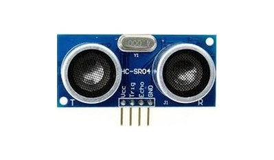
Second is the HC-SR04 ultrasonic distance sensor. Although fine for prototyping, it’s a 5 V module, lacks temperature compensation and other features that’d be needed outside a temperature-controlled room. Here ST’s VL53 Time-of-Flight sensors are a good alternative, containing a range of sensors of which we covered the fancier VL53L5CX previously for 3D scanning a room. Of course, you can also use reflective IR as a good cheap alternative.
Third is the HC-SR501 passive infrared (PIR) motion module. This one is also fine for PIR and motion sensing prototyping, but is too inconsistent and power-hungry for production. Instead you can get much better and much smaller PIR modules, like the Panasonic EKMC and EKMB, or the ST STHS34 IR motion and presence sensor.
Fourth takes a swing at all the MQ-series of gas sensors. These generally feature a heater that consumes a lot of power, require a long burn-in period and need calibration using a reference gas to be useful. In a safety-first environment you’d thus use a sensor from a reputable manufacturer with a datasheet and some level of calibration.
Fifth is the MPU-6050 IMU, which probably comes as a surprise to many, as it generally seems to just work well. The main issue here is something that is common for a lot of common non-sensor chips as well, like the still very common UDA1334A I2S codec that hasn’t been manufactured by NXP for ages, but is still found everywhere. If you want to design a product that can be easily manufactured, you have to pick an IMU here that is actively being manufactured by a reputable manufacturer.
You also have to actively avoid anything that’s marked as ‘Not Recommended for New Designs’ (NRND) unless you love supply surprises during production. For IMUs you end up with something like the Bosch BMI270 or TDK’s ICM-42688, albeit for more money, but with better specifications.
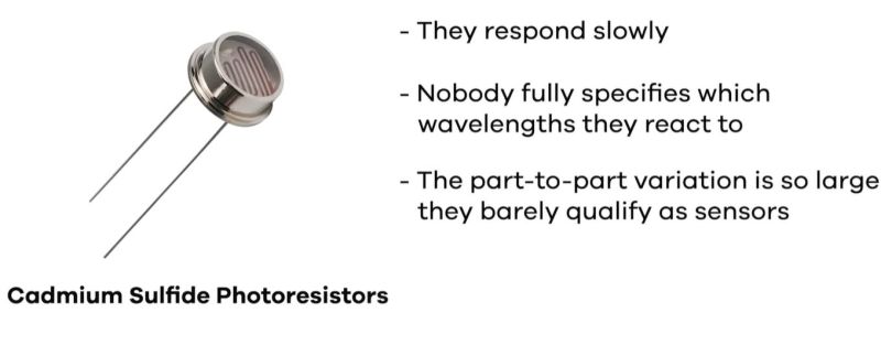
Sixth sensor are cadmium sulfide photoresistors (LDRs). Although this is a very simple light-dependent resistor part, they fall afoul of the EU’s RoHS regulations due to the presence of said cadmium. Fortunately they’re not that great anyway, so an ambient light sensor IC is a good alternative. Here the Vishay VEML7700, TI OPT3001 and Lite-On LTR-303 are recommended and provide far more features at a reasonable BOM cost.
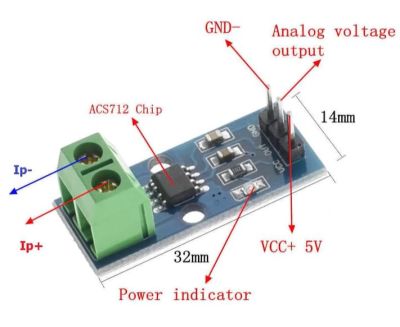
Seventh sensor and #1 on the list is the ACS712 current sensor. Specifically the mains-targeting breakout boards that are being sold everywhere. Here it’s not the IC that’s the problem, it’s that here – as also seen with various common relay boards – there has been no consideration given to basic mains power safety, such as creepage distance and general separation. The lesson here is that if you integrate mains power in your device, you do not skimp on safety with a sketchy module.












Anything involving mains power requires proper separation and is not recommended for hobbyist tinkerers, even the experienced one make many mistakes here.
It used to be a standard first project to build an AC to DC powersupply. Wall warts and power bricks weren’t common back then. If you needed more power or a longer run time than batteries could supply, you built your own power supply.
They used to sell AC powered kits for hobbyists to assemble.
Are people these days incapable of following simple safety rules?
“Are people these days incapable of following simple safety rules?”
Consider the quality of most yoootooob videos.
Consider hardware hallucinated by LLMs.
Consider that in the UK tiktok has a lot of TV adverts where a rap artist claims his tunes help people under science. (IIRC understanding mains fuses is an example)
People don’t realise ther are rules, therefore can’t understand them, therefore can’t follow the rules.
Welcome to the idiocracy.
well, darwin will have an awful lot of reasons to smile…
I’m not sure the AC/DC converter circuits in the magazines and books of the 80s/90s were safe even if you followed the instructions. Especially as they’d likely have been built on veroboard (stripboard) because custom PCBs was expensive and difficult (and nasty chemicals).
Though maybe they were safe enough as they’d likely have been built around a transformer which I guess made isolating the mains voltage easier, but also made them inefficient.
The mains voltage regulators were very simple: 5V 1A regulator = Transformer, bridge rectifier, capacitor, LM309 in TO-3 package.
and – 12V or 15V or 18V: Transformer, 2 diodes in voltage doubler, 2 caps with the doubler center as ground, 2 x LM741 with power transistors as the regulators. Zeners or a diode or ??? as reference.
There typically wouldn’t be any mains voltage on the circuit board. The fuse holder, switch & transformer would be wired point to point. There wouldn’t be any safety issues as long as the builder followed the instructions.
“Are people these days incapable of following simple safety rules?”
People these days are incapable of learning simple safety rules.
They will do whatever the AI tells them to with no thought or reasoning.
There’s no need to learn anything in advance anymore, just go to any online form, ask them to do your homework, and some dozen or two helpful idijits will do their homework (only to later complain schools don’t teach anymore and it’s their fault)
Those power supply kits are still around, but no one wants to spend an extra dollar or two to buy from manufacturers with a reputation. aliexpress and ebay all the way! So when whatever random 12v input transformer is tossed in the kit and gets plugged into 120v, well obviously the outcome could never have been predicted /s
You’re asking tthat about a generation who swallowed Tide pods..
To be fair, that generation was raised by parents who put cancer warnings on sawdust and content warnings on Sesame Street:
https://www.p65warnings.ca.gov/businesses/sample-warnings-and-translations-businesses/wood-dust-exposure-warnings
https://www.cbsnews.com/news/sesame-street-for-adults-only/
Kids raised in that kind of environment can fail to develop an ability to assess risk. When you’re surrounded by “”Warning: cedar shavings” and “Warning: Cookie Monster has bad dietary habits”, it can take the edge off the one that says, “Warning: 100kV”.
Yet that generation smokes and drinks less than past generations, votes to keep the right out of office and is more progressive, diverse and inclusive. Given these facts, why do you doubt their critical reasoning?
Not knowing the difference between a man & a woman does not inspire confidence in critical thinking skills.
Now brought to you by the same people: adultism
from google: prejudice, discrimination, or a biased power dynamic where adults assume they are superior to young people and are entitled to act upon children without their agreement.
Steven, why do I need to come up with a definition for other people’s identities? Just ask them directly then respect it. Adultism is very real, supported by scientific literature and you’re demonstrating it right now.
Heathkit showed the way to do something in a safe manner for a particular public.
True, but the mains powrered kits contained a transformer (a relatively large one for 50Hz or 60Hz power) that provided good safety isolation. These days the switch mode supply is more usual but definitely not a project for a beginner.
There is a happy medium to be had between the exclusive club of people who already knew they wanted to learn electronics and were willing to seek out the knowledge required to understand things, and the push-button using group of witless magical box users who understand nothing.
Modern (non AI) tools and sources can do a great job of showing people that a thing they thought was complicated is actually interesting, and lead them a bit more gently into studying something useful.
Can we have a list, so I don’t have to watch the video? Kthxbye.
Actually there is a list. Clearly I didn’t even look. Thanks.
TL;DR
7) DHT11/DHT22 environmental sensors, use the SHT40/41, HDC4020, BME280
6) HC-SR04 Ultrasonic Distance Sensor, use the VL53 ToF, a MaxBotix Ultrasonic sensor, or a IR sensor
5) HC-SR501 PIR module, use the Panasonic EKMC and EKMB or STHS34
4) MQ-2 and MQ-135 Gas sensors, use the Sesnirion SGP50 SGP41 SCD40 SCD41 or certified cells from SpecSensors or Figaro
3) MPU-6050 IMU, use the ICM-42688, BMI270, LSM6
2) Cadmium Sulfide light sensor, use the VEML7700, OPT3001, LTR-303
1) ACS712 Current Sensor, use the AMC1302, a current transformer, ACS37800, or certified energy metering module
But we still don’t know which one is BANNED. With capital letters!
Number 2 due to Cadmium.
Bought an SCD40 on Aliexpress and its temperature sensor is so bad that I have to trim it every few degrees to get accurate humidity readings. This is made even worse by its command set, which requires measurements to be turned off to set the temperature correction value, because when you switch measurements back on, it takes several minutes for them to settle.
The low power periodic measurement mode is what I use and setting the temperature-offset is what I meant with trimming.
rtc: ds1307 vs. ds3231
Details?
More of these articles please, useful summary no need to watch an algorithm satisfyig video… Hackaday at its best ;-)
Yes! Ideally, could we have a common parts library including things to avoid? I feel the hurdle to find what I need for tinkering projects a bit high and to dive into each datasheet before even understanding the main needs as well, while in the other side not wanting to solely rely on breakout bords
It’s a shame about CdS cells, but I had a hard time finding them even 15 years ago. I often ended up doing hacker type stuff with them by replacing the potentiometer in a mains dimmer with them then and shining an Arduino LED at them for isolated mains light dimming. But cadmium is bad stuff. Too bad the coat most fasteners in jets with it 🫤
I’m sure they can, and do, put kilograms of cadmium in the weapons they give to ukr*ne, and then are fine if it covers half of the EU with a layer of the stuff.
Just as long as people don’t use a part with 0.00000000001 gram of the stuff, encased in resin.
Well, the wepons get rid of both banderites and ruskies so that’s a net positive for the world. With cadmium photcells what can you do? Poison your co-worker’s coffee?
Grind them down and make your own paint pigments? Just don’t lick your brush…
RE: banderites fine word to describe yourself with, too.
weren’t they the scanning sensor in the first primitive mechanical televisions? if that is true, they must be faster than is implied by the video narrator (not an AI in this case!)
Selenium.
CdS has a weird frequency response. As I recall, you’d be hard pressed to get low MHz out of it (early TV would need at least, what, 100s kHz?), but the real oddity is the ~sqrt(1/f) recovery, i.e. it’s not flat up to a corner but has a long tail (how much amplification are you willing to throw at it to compensate)?
There was also Se photocells, which I know nothing about as far as characteristics, but maybe they were faster, and which one(s) were used was misremembered? (I haven’t read about early TV in a long time, I don’t remember myself.)
I had to work with CdS sensors about 40 years ago, and learned a bit about them. They’re photo-resistors, the most sensitive type commonly available. Light generates electron-hole pairs which enhance the conductivity of the material. The high sensitivity is due to the long lifetime of those pairs. The poor frequency response is also due to the long lifetime.
Compared to silicon processes, CdS sensor manufacturing is incredibly sloppy. That sloppiness, combined with the inherent difficulty of controlling carrier lifetime, means that characteristics cannot be well controlled. Basically, the chemicals making up the sensor are poured into a vat along with some liquid carrier that is later evaporated. The slurry in the vat is thoroughly mixed, then painted, silk-screened, or otherwise applied to an insulating substrate. To provide some humidity protection, the sensor might be covered with a clear substance.
CdS are the best sensor to breadboard, I have to laugh at the eco FUD over them. More cadmium is found in cheap jewelry. Then there are the cheap electrolytic caps causing products to end up in the trash, e-waste is many times worse.
Funny thing, newer mains nightlight using CdS cell works by the cell shorting out the bulb in daylight. LOL. It makes heat during the day. That had me praising the Great Leap Ahead.
If the nightlight use LEDs, then the CdS shorting them is useless. A LED driven with few mA will last forever. Before high efficiency LEDs the nightlight had a neon bulb. CdS was used to extend the limited working life of the neon bulb.
The CdS is connected to a transistor. When the CdS passes enough current (ie it’s now daytime) the transistor turns on and shorts the LEDs. Simple, cheap, and yeah well it works.
So by running the power thru the transistor rather than the LEDs it uses the same amount of power (arguably bugger all) whether the light is on or off.
with a capacitive dropper the current will stay mostly the same, but cos Phi will go down, so less energy consumed, and no need to deal with “high” voltage switches
Good article!
If only we had a similar list for software libraries!
We do – it’s called “github”.. :)
So we shouldn’t use libs that are on github? That’s actually quite sensible advise!!
John Teel’s videos on YouTube all contain first class advice on how to go about building a real product intended for production and sale in volume as opposed to building one-offs to play with on your bench.
I can’t agree with him on the HC-SR04 ultrasonic modules.
His first issue is that they are 5v parts, I rarely work at anything other than 5v.
He mentions the accuracy, who is expecting precision with a sensor that works in air? I have been using these sensors for as long as they have been available, even started out with the polaroid transducers and they are great. I don’t need to know anything other than relative measurements for robotics. He mentions IR as an alternative, but this is affected by ambient IR and the colour of the object being measured.
Add to that the expense of Maxbotics sensors and you can’t go past a sensor that costs $3.
5V in production designs is on its way out, though. If you need anything that has a bit of oomph (so STM32, ESP32, …) it’s gonna be a 3.3V part. AVRs and such are still 5V, but relatively expensive for what they provide. Secondly, the time-of-flight sensors like the VL53L5CX mentioned actually are great parts that don’t have the downside of the classic line-CCD-based distance sensors: they’re pretty resistant to both ambient light as well as color differences of the object measured.
The CH32V0 microcontrollers can run from 5 volts. They are much cheaper and more powerful than AVRs.
Many of the STM32 microcontrollers have some pins that are tolerant of 5 volt inputs.
When speaking about processing and sensory applications. That is definitely a domain where 3.3V is the default rail. Especially since it is a very convenient voltage to power from stuff like batteries and somewhat easier to achieve efficiency with.
But while great for that. 3.3 does tend to fall short of getting most FETs nice and saturated. With a lot of H-Bridge drivers, FETs and similiar (even newly designed) still really wanting that 4.5v minimum. Plus there are also just the sheer amount of busses that use 5V. Including the one that is connecting the very thing i’m typing on to my PC: USB. Making it the go-to for USB powered stuff.
Which you encounter more often really depends on what you are doing. One could genuinely work almost exclusively with 5V and another with 3.3V.
That aside. I indeed don’t see much reason to use that old kind of sonar sensor in this day and age.
I have a soft spot for the old sonar modules, but i honestly wouldn’t use them anymore.
We have gone a freakishly long way from those old bulky IR range-finders that could only do like 30cm tops and failed if you so much as pointed a red light at it. The average ToF sensor of today is tiny, affordable, Immune to such interference and often gives you multiple separate zones giving you also directional information. I generally find it worth to use these even if it requires a shifter for a 5v controller.
When will those silly clickbait titles ever stop? With a title of “7 sensors you should never use in a product” I’m really wondering who this is for? For the people who do not know anything about electronics but yet feel confident enough to make a product?
The problem is not the part, the parts are fine, the problem lies within the lack of knowledge in how to use them. Every sensor has it’s problems, read the datasheet and learn the part before you start using it in something that needs to be reliable. If a part doesn’t have a decent datasheet… that’s a big red flag and you should think about not using it.
DS18B20 as a probe with stainless-steel capsule and fixed cable: I tried multiple sources, the devices were always fake. The issue was less with the accuracy, but more with the protocol itself: I had one unit that spew CRC errors. Worse, sometimes the CRC was right and the measurement was off by 1000 Kelvin.
Unfortunately, I have no idea where to get a genuine DS18B20 in a probe. So better use a Pt100 + 4-wire cable, I guess. sigh
Every time I see an EU regulation as being a reason to avoid something I thank providence I am not European.
Hey, yeah. They are trying to protect the people and environment of the EU from poisons and long term problems. Can’t have that kind of communist shit. Gotta let capitalists rape the world and poison everyone like god intended.
Nice article. Thanks for listing all the useful and not so useful sensors. I’ve been using an HC-04 as a proximity “radar” scanner for a little robot that I use to annoy the cat. It works, but has limited range to avoid obstacles at higher speeds. I would like to have more range so that it could read the furniture (and the cat) better. I am going to try a couple of the sensors in the article and see how they do.
And then hook up a water pistol to the thing. My cat already has attacked the robot. I need it to get away quickly. lol
When I read the title I said aloud to myself, “HC-SR50x” (501 and the smaller 505). I tried everything to make them work for presence detection. Their accuracy at any given time is a coin flip. Instead I pivoted to rcwl 0516 microwave sensors. Which initially were too accurate. But with some resistors and shielding they work phenomenally.
I think the best “avoid this” advice I could give is to throw out any Dupont jumper you get for free, the female connectors are good for one plug before they lose all retention.
I’m guessing that you did not read the data sheet. The 712 is rated for BI, at less than 300Vrms operational. This particular model is not intended to provide safe seperation and isoloation for human touch from mains voltage. But you are correct that most of these cheap boards make its use even more risky. That said, I’ve used the 712, and similar, for many years. Very simple and reliable. But my designs do not depend on the IC for protecting a human from mains voltage.
A good tool to check if parts are still current is octopart ?https://octopart.com/