Every experienced machinist knows the value of taking regular measurements. If one works carefully and checks dimensions frequently, it’s possible to make a part much more precise than could be made by relying on the machine’s accuracy alone. In a similar vein, it’s possible to make a measuring device out of comparatively crude parts, as long as their behavior is well understood. Related to both principles is [BubsBuilds]’s displacement sensor, which uses a 3D printed frame but reaches precision better than two micrometers.
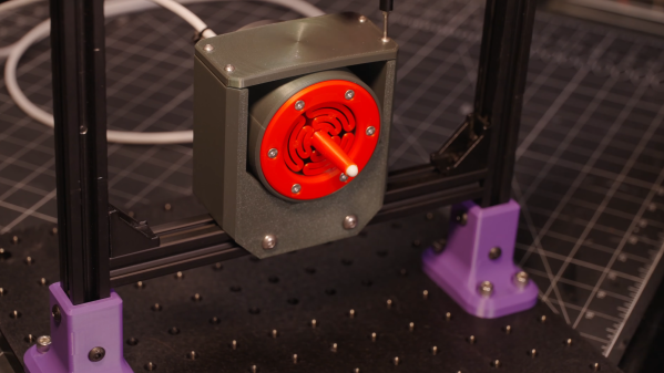
Admittedly the printed parts aren’t the source of the sensor’s precision, that comes from an opto-interrupter. This design has a central stylus, one end of which contacts the object under measurement. The other end flattens to a knife-edge blade, which fits between the diodes of the opto-interrupter. As the stylus point is pressed in, the blade blocks off more light from reaching the photodiode, creating an output signal proportional to displacement. To keep the stylus from twisting or moving side-to-side, two flat, circular flexures hold the stylus in the center of a cylindrical housing.
[Bubs] printed several flexure variations to see how well they resisted and permitted various torques and forces, and a symmetrical flexure design proved best for his purposes. Once the sensor was assembled, he tested it against the measurements recorded by a laser confocal displacement sensor. This design was an update from a previous version, and it improved in a few regards: the non-linearity had decreased, and the repeatability was now better than two microns, though the range had been halved. Significantly, though, it’s now much easier to mount, making this an actually practical tool.
If, however, this doesn’t fit your needs, there are many other ways to build a linear displacement sensor, ranging from capacitive to magnetostrictive. On the manual side of things, we’ve also covered a comparison of calipers.
Continue reading “Building A Micrometer-Level Displacement Sensor With 3D Printed Parts”