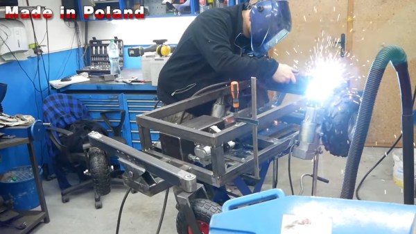
Hydraulic gear pumps are deceptively simple: just two gears rotating together, forcing the hydraulic oil from one side to the other where the teeth don’t meet, and thus providing the ability to pressurize said oil to make hydraulic cylinders, final drives, etc. do their thing. As with most machining projects like this, the devil is absolutely in the details, particularly in the tolerances. This is the crash course that the [Artisan Makes] channel on YouTube is currently going through.
In this part one of a series on a DIY gear pump, scrap aluminium is used for the housing, along with 1045 medium carbon steel for the gears and W1A high carbon steel for bearings and other wear surfaces. Since at least one of the gears needs to be driven, a lip seal rated for 10 bar is used to provide a path for the shaft. As noted in the video, this is supposed to be a learning experience, ergo it’s a simplified design that merely targets being functional as a gear pump.
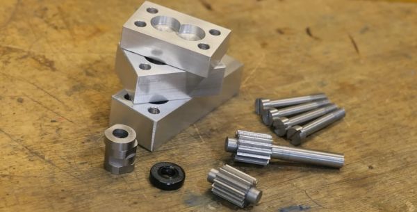
With the basic design figured out, the parts were created on the lathe and mill, followed by assembly. Most of the controversy is about the tolerances within the housing, as any leakage will reduce the efficiency. This means the spacing between the gears and housing, space between the gears and bearings, as well as that provided by the gasket that seals the housing base and top. This is where the comment section somewhat explodes with criticism and advice.
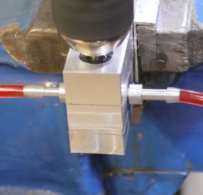
As can be seen in the demonstration with a better gasket, there is absolutely flow when driven at 1200 RPM, but also clearly severe leakage as evidenced by said flow not moving quite as fast as it should. We’re looking forward to the next part, in which addressing these tolerances is tackled, with hopefully a much more performant gear pump resulting.
Continue reading “Building A Hydraulic Gear Pump Isn’t So Easy”