[Ken Shirriff] Demystifies BeagleBone I/O

If you have ever spent a while delving into the bare metal of talking to the I/O pins on a contemporary microprocessor or microcontroller you will know that it is not always an exercise for the faint-hearted. A host of different functions can be multiplexed behind a physical pin, and once you are looking at the hardware through the cloak of an operating system your careful timing can be derailed in an instant. For these reasons most of us will take advantage of other people’s work and use the abstraction provided by a library or a virtual filesystem path.

If you have ever been curious enough to peer under the hood of your board’s I/O then you may find [Ken Shirriff]’s latest blog post in which he explores the software stack behind the pins on a BeagleBone Black to be of interest. Though its specifics are those of one device, the points it makes have relevance to many other similar boards.

He first takes a look at the simplest way to access a Beagle Bone’s I/O lines, through virtual filesystem paths. He then explains why relying so heavily on the operating system in this way causes significant timing issues, and goes on to explore the physical registers that lie behind the pins. He then discusses the multiplexing of different pin functions before explaining the role of the Linux device tree in keeping operating system in touch with hardware.

For some Hackaday readers this will all be old news, but it’s safe to say that many users of boards like the BeagleBone Black will never have taken a look beyond the safely abstracted ways to use the I/O pins. This piece should therefore provide an interesting education to the chip-hardware novice, and should probably still contain a few nuggets for more advanced users.

We’ve seen a lot of [Ken]’s work here at Hackaday over the years, mostly in the field of reverse engineering. A few picks are his explanation of the TL431 voltage reference, a complete examination of the 741 op-amp, and his reverse engineering of the 1970s Sinclair Scientific calculator.

We appreciate [Fustini]’s tip on this story.

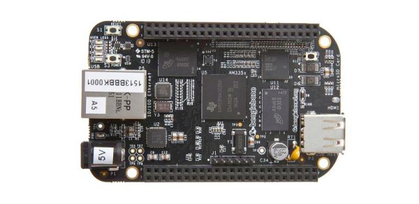
BeagleBone Black image: BeagleBoard.org Foundation [CC BY-SA 3.0], via Wikimedia Commons.

Remove Your Arduino’s External Oscillator To Gain A Free Pair Of IO Pins

2free-arduino-io-pins

[Mark] from SpikenzieLabs was wrapping up a project using an Arduino the other day and found himself in need of a few more I/O pins. He could have added extra circuitry to the project, but he decided to see if he could gain a few pins by removing a few components instead.

He put together one of his Minuino boards, but rather than installing the crystal and its associated capacitors, he added a couple of pin headers in their place. It’s well known that the internal clock on the chip is not as precise as a crystal, but [Mark’s] project was not that time sensitive, so he had no problem sacrificing the oscillator for a few extra pins.

With his new I/O pins in place, he merely needed to tell the ATmega chip which clock it should be using, and he was well on his way. While this might not be the best solution for all projects out there, if you are building something that values pincount over precision, this hack is for you.

Check out the video below to see [Mark’s] hack in action.

[via HackedGadgets]

Continue reading “Remove Your Arduino’s External Oscillator To Gain A Free Pair Of IO Pins”

All Your I/O Pins Belong To ArduinoDashboard

arduino_dashboard

So if you’re knee deep in an Arduino-based project and you want to constantly monitor all of the micro’s pins, what’s the best way to go about it? [Jonathan Clark] from LVL1 in Louisville was looking to keep a closer eye on his board and whipped up an application he calls ArduinoDashboard.

Programmed in Processing, the application gives you a look at all of your Arduino board’s analog and digital pins in a simple to use display. All that’s required to run the application is a bit of code inserted at the top of your sketch, which can be called anywhere in your program’s loop. Once the code snipped is called, all of the board’s pins are read and the data is sent to your PC.

ArduinoDashboard is still very much in beta at the moment, but it looks to be stable enough for everyday use. [Jonathan] has plenty of improvements and new features in mind, so be sure to check back often to see what’s changed.

[via Adafruit Blog]