
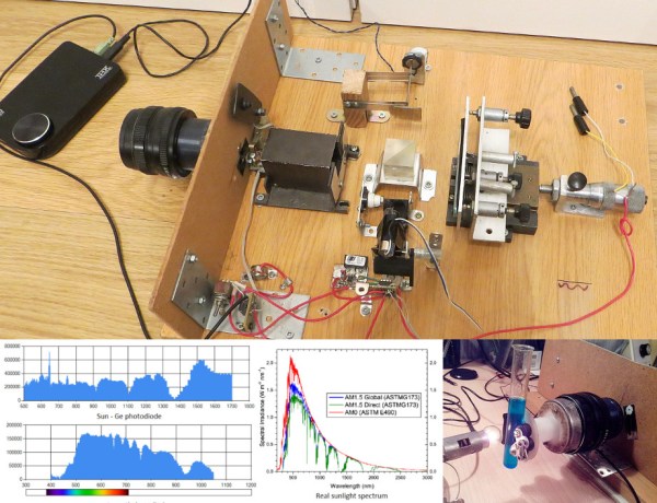
Typical spectrometers use prisms or diffraction gratings to spread light over a viewing window or digital sensor as a function of frequency. While both prisms and gratings work very well, there are a couple of downsides to each. Diffraction gratings produce good results for a wide range of wavelengths, but a very small diffraction grating is needed to get high-resolution data. Smaller gratings let much less light through, which limits the size of the grating. Prisms have their own set of issues, such as a limited wavelength range. To get around these issues, [iliasam] built a Fourier transform spectrometer (translated), which operates on the principle of interference to capture high-resolution spectral data.
[iliasam]’s design is built with an assortment of parts including a camera lens, several mirrors, a micrometer, laser diode, and a bunch of mechanical odds and ends. The core of the design is a Michelson interferometer which splits and recombines the beam, forming an interference pattern. One mirror of the interferometer is movable, while the other is fixed. [iliasam]’s design uses a reference laser and photodiode as a baseline for his measurement, which also allows him to measure the position of the moving mirror. He has a second photodiode which measures the interference pattern of the actual sample that’s being tested.
Despite its name, the Fourier transform spectrometer doesn’t directly put out a FFT. Instead, the signal from both the reference and measurement photodiodes is passed into the sound card of a computer. [iliasam] wrote some software that processes the sampled data and, after quite a bit of math, spits out the spectrum. The software isn’t as simple as you might think – it has to measure the reference signal and calculate the velocity of the mirror’s oscillations, count the number of oscillations, frequency-correct the signal, and much more. After doing all this, his software calculates an interferogram, performs an inverse Fourier transform, and the spectrum is finally revealed. Check out [iliasam]’s writeup for all the theory and details behind his design.
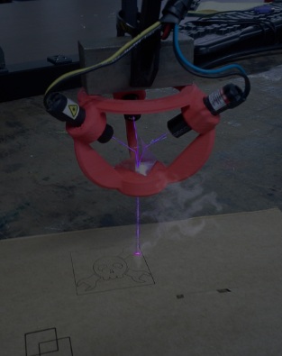 [Sp4rky] got his laser diode modules out of surplus medical equipment and, unfortunately, the rated optical wattage was quite low. Since he had 3 diodes, he decided to try to combine the 3 low power beams into one high power beam. This can be done using a prism. A prism splits sunlight into a rainbow of colors because each wavelength(color) of light that passes through the prism is bent a different amount. Since the laser diodes only put out one wavelength of light, the beam bends but does not split or diffuse. A 3D printed bracket points each laser diode at a 3-sided pyramidal prism which sends the combined beam of light straight out the bottom towards the object to be cut or engraved.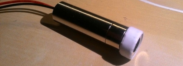

 If you already have a 3D printer, you already have a machine that will trace out gears, cogs, and enclosures over an XY plane. How about strapping a laser to your extruder and turning your printer into a laser cutter?










