Laser pointers were cool for about 30 seconds when they first came out, before becoming immediately passé and doing absolutely nothing to improve the boss’s quarterly reports presentation. However, just as with boom boxes and sports cars, more power can always make things better. [Styropyro] was unimpressed with the weak and unreliable laser pointers he’d sourced from eBay, so gutted one and began a fresh build.
After fiddling with some basic 1mW eBay green lasers, [styropyro] had some fun turning up the wick by fiddling with the internal trimpots. This led to the quick and untimely death of the cheap laser diodes, leaving a compact laser pointer shell ripe for the hacking.
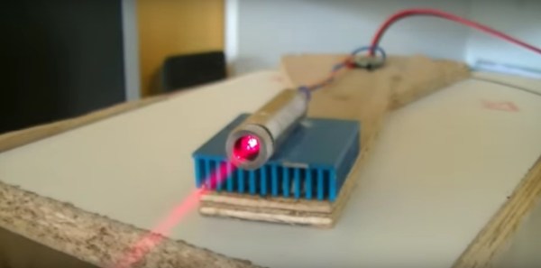
To replace the underwhelming stock components, [styropyro] chose a Nichia NDG7475 high-powered laser diode, fitting it into a small heatsink for thermal management. Current draw was far too high to use the original switch, so the stock housing’s button is instead used to switch a MOSFET which delivers the full current to the laser driver. To reach the higher output power of 1.4W, the laser diode is being run over specification at 2.3 amps. All this current draw would quickly overwhelm standard AAA batteries, so a pair of lithium polymer 10440 batteries are substituted in to do the job.
The build shows that with clever parts selection and some easy hand soldering, you too can build an incredibly dangerous laser pointer at home, that fits neatly in your shirt pocket. Alternatively, you might prefer something on the larger scale. Video after the break.
Continue reading “Building A 1.4W Laser Pointer In A Tiny Housing”