Air Wrench Becomes A Milling Machine Power Drawbar

We sometimes wonder if designers ever actually use their own products, or even put them through some sort of human-factors testing before putting them on the market. Consider the mechanism that secures toolholders to the spindle of a milling machine: the drawbar. Some mills require you to lock the spindle with a spanner wrench, loosen the drawbar with another wrench, and catch the released collet and tool with – what exactly?

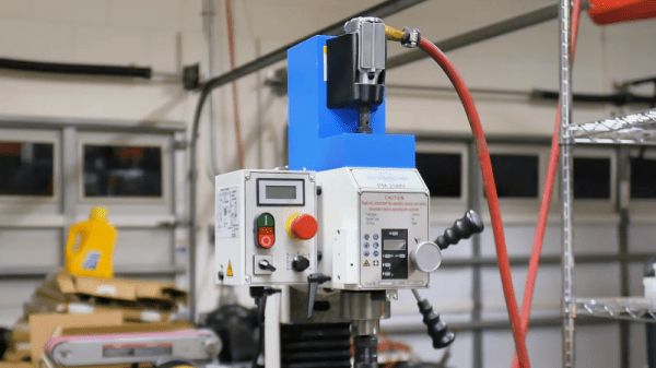
Unwilling to have the surgical modifications that would qualify him for the Galactic Presidency, [Physics Anonymous] chose instead to modify his mill with a power drawbar. The parts are cheap and easily available, with the power coming from a small butterfly-style pneumatic wrench. The drawbar on his mill has a nearly 3/8″ square drive – we’d guess it’s really 10 mm – which almost matches up with the 3/8″ drive on the air wrench, so he whipped up a female-to-female adapter from a couple of socket adapters. The wrench mounts to a cover above the drawbar in a 3D-printed holster. Pay close attention to the video below where he goes through the Fusion 360 design; we were intrigued by the way he imported three orthogonal photos on the wrench to design the holster around. That’s a tip to file away for a rainy day.

This is a great modification to a low-cost milling machine. If you’re in the process of buying machine tools, you should really check out our handy buyer’s guides for both milling machines and lathes. It’ll let you know what features to look out for, and which you’ll have to add later.

Continue reading “Air Wrench Becomes A Milling Machine Power Drawbar”

Hackaday Links: May 18, 2014

hackaday-links-chain

Think the original Pong is cool? How about point to point Pong? [v8ltd] did it in three months, soldering all the leads directly to the chip pins. No sockets required. It’s insane, awesome, a masterpiece of craftsmanship, and surprising it works.

[Jeremy Cook] is building a servo-powered light graffiti thing and needed a laser diode. How do you control a laser pointer with a microcontroller? Here’s how. They’re finicky little buggers, but if you get the three-pack from Amazon like [Jeremy] did, you get three chances to get it right.

NFC tags in everything! [Becky] at Adafruit is putting them in everything. Inside 3D printed rings, glued onto rings, and something really clever: glued to your thumbnail with nail polish. Now you can unlock your phone with your thumb instead of your index finger.

Photographs capture still frames, but wouldn’t it be great if a camera could capture moving images? No, we’re not talking about video because this is the Internet where every possible emotion, reaction, and situation can be expressed with an animated GIF. Meet OTTO, the camera that captures animated GIFs! It’s powered by the Raspberry Pi compute module, so that’s interesting.

[Nate] was getting tired of end mills rolling around his bench. That’s a bad thing. He came up with a solution, though: Mill a piece of plywood into a tray to hold end mills.

The Da Vinci printer, a printer that only costs $500 because they’re banking on the Gillette model, has been cracked wide open by resetting the DRM, getting rid of the proprietary host software, and unbricking the device. Now there’s a concerted effort to develop custom firmware for the Da Vinci printer. It’s extraordinarily bare bones right now, but the pins on the microcontroller are mapped, and RepRap firmwares are extremely modular.

PCB Milling Tutorial

[Juan Jose Chong] put together a set of videos and a PDF guide to milling printed circuit boards. You’ll find the pair of videos, totaling about twenty-two minutes, embedded after the break. In them, [Jaun] details the techniques used by the IEEE chapter at Texas Tech University to mill PCBs instead of using the traditional method of etching them. We’ve long been a fan of milled PCBs and often dream about the day we can retire the old iron we use for the toner transfer method.

In the tutorial, IsoPro is the software used to control the mill. The CAM files from a PCB design program are imported – they can come from many different programs including EagleCAD. A few setup steps let the operator configure the resolution necessary to mill the correct tolerance and from there the paths that outline each trace are calculated in software. In order to facilitate double-sided boards a reference hole is drilled in the copper clad board to accept a post on the mill table. Tape down the substrate with some foil tape, set the depth of the end mill bit, and let the machine do its thing. [Juan’s] video illustrates how quickly this can produce a rather complicated board, finishing in around 20 minutes.

Continue reading “PCB Milling Tutorial”