A newly licensed amateur radio operator’s first foray into radios is likely to be a VHF or UHF radio with a manageable antenna designed for the high frequencies in these radio bands. But these radios aren’t meant for communicating more than a double-digit number of kilometers or miles. The radios meant for long-distance communication use antennas that are anything but manageable, as dipole antennas for the lowest commonly used frequencies can often be on the order of 50 meters in length. There are some tricks to getting antenna size down like folding the dipole in all manner of ways, but the real cheat code for reducing antenna size is to build a loading coil instead.
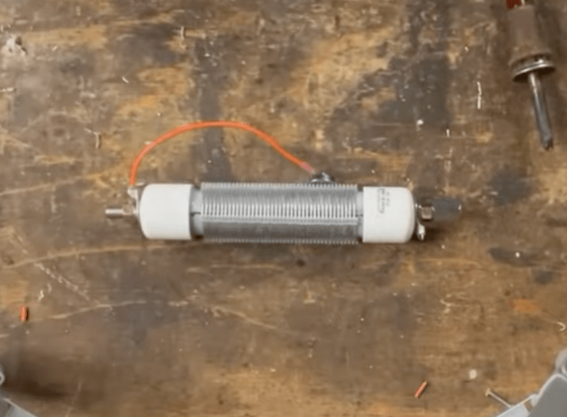
As [VA5MUD] demonstrates, a loading coil is simply an inductor that is placed somewhere along the length of the antenna which makes a shorter antenna behave as a longer antenna. In general, though, the inductor needs to be robust enough to handle the power outputs from the radio. There are plenty of commercial offerings but since an inductor is not much more than a coil of wire, it’s entirely within the realm of possibility to build them on your own. [VA5MUD]’s design uses a piece of PVC with some plastic spacers to wind some thick wire around, and then a customized end cap with screw terminals attached to affix the antenna and feedline to. Of course you’ll need to do a bit of math to figure out exactly how many turns of wire will be best for your specific situation, but beyond that it’s fairly straightforward.
It’s worth noting that the coil doesn’t have to be attached between the feedline and the antenna. It can be placed anywhere along the antenna, with the best performance typically being at the end of the antenna. Of course this is often impractical, so a center-loaded coil is generally used as a compromise. Coils like these are not too hard to wind by hand, but for smaller, lower-current projects it might be good to pick up a machine to help wind the coils instead.


This guy uses a movable tap to short out unwanted turns to reduce coil inductance. You can find similar topology in the tank circuits of old tube transmitters where a progressively-shorting rotary switch is used as a “band switch”.
What bothers me is this: Why not simply tap the coil, leaving the unwanted windings to float. Why short them? Why wouldn’t the shorted turns–still in the field of the coil–waste energy and lower the overall Q?
Builders of sliding receiver coils (like you find on antique crystal radio receivers) went to great lengths to try to engineer sliders to rest on only one turn at a time. A slider contacting two turns created a defacto shorted turn and reduced selectivity Q.
Perhaps the reduced Q in the case of the transmitter is considered a “benefit” because it increases bandwidth?
Any silver-haired Elmers care to weigh in?
To me it’s a pure benefit in a few regards. Many mobile/portable HAMs who deploy short antennas requiring coils like these to hit lower bands, do not have tuners in their kit, meanwhile the radios they use do have highly selective filtering options. Greater bandwidth means not needing to go back to the antenna and fuss with precision when QSYing within the same band and keep an optimal tune.
The magnet-style tap is far easier to adjust when wearing gloves out in the cold as well.
Ham…just say ham.
Thanks but I did that for non-ham readers to distinguish the noun context easier.
Will it handle legal limit?
It’s 18 gauge wire so your guess is as good as mine. Mainly designed for portable use and personally I prefer a resonant antenna with high power.
” Why not simply tap the coil, leaving the unwanted windings to float. ”
Well then you would have a step up auto-transformer. i.e. extremely high voltages on the open end.
Actually it’s a bit worse than that. Due to C, the open end can the become resonant driving the voltages even higher.
Luckily this arrangement has a name: It is called a Tesla Coil.
So yeah, we short the open end.
That makes sense. Thank you.
In addition, shorted turns result in a circulating current in them. This current creates a counter inductance that bucks the original. The net result is reduced inductance which is the goal to start with.
The best variable inductors actually wind the unused wire on an aluminium cylinder, one of the reasons is that for a large frequency range the unused coil can have a self resonance on a harmonic frequency. Shorting or eliminating may give some additional losses but is safer in general.
How about a 160M mobile version?
http://www.craigwilliams.com/radio/mobile/160meter/index.html
The typical coil design circuit will let you calculate the inductance based on the turns, diameter, and so on… but that’s usually not what you want. To design a coil, typically you know the inductance and would like a coil that maximizes Q (or minimizes cost or size or something).
If you know what inductance you need, and would like to design a coil to meet those needs, I have a library of programs that will help. You can scan through all diameters and lengths, the program will interpolate the number of turns needed to achieve the required inductance, and then you can plot the results and select the best coil.
https://hackaday.io/project/193000-inductance-design-tools
For example, you can scan through all diameters and lengths (interpolating the target inductance), then plot the Q using gnuplot and choose the parameters that give the best Q.
Or you could do the same thing to choose the smallest length of wire, or shortest coil length, or whatever.
The library also takes frequency into account (such as skin effect), so if you know your frequency of use it will tell you the inductance at that frequency. The standard formula is for audio frequencies, and is only accurate out to about 100 KHz.
It’ll also tell you if the target frequency is lower than the self-resonant frequency of the coil, which means you should use a different set of parameters.
For the coil in the article, be sure that the coil has a *low* Q value. The voltage across the coil will be the input voltage times the Q value at that frequency, so if you should happen to make a high-Q coil, transmitting on the exact resonant frequency of the antenna/coil combination can put a very high voltage across the coil, potentially burning it out.
Because of my QTH situation, I will be using and coax feed to and end fed Zepp that has a run of ~ 60′ so I may just add the loading coil at the end of the Zepp’s run not caring so much getting out on 80 meters. I am excited about getting back on the air after QRT for ten years. I’m a CW op but with this new YAESU rig with an auto turner, it will be fun and with my new PC, I will try my hands at RTTY. 73 AA0PP, Chesterfield Missouri
It is absolutely not true that the best place for the coil is at the end of the antenna. I don’t know where he got that idea but it’s false. Current along the antenna wire does the radiating, with the best radiation occurring when the current is spread over the longest length of wire commensurate with other considerations … physical space, tuning, etc. If you put the coil near the feedpoint the coil constrains the current distribution to the coil … resulting in the remaining wire having relatively less current to actually radiate. If you put the the coil at the far end of the wire, there is almost no current there so the coil is virtually useless. If used, coils are optimally put somewhere in the middle of the wire as a best-case compromise. This can all be easily verified with an antenna modeling program like EZNEC or similar.
As an aside, there are probably thousands of antennas out there with loading coils, many of them hand made like this one. Categorizing this as a hack is on par with using a credit card to scrap snow off your windshield.
“Categorizing this as a hack is on par with using a credit card to scrap snow off your windshield.” — ouch!! Perhaps think of it as a tutorial rather than a hack? I found the recap (and the corrections in the discussion re. coil placement) helpful, and its motivated me to get the bits together to have a go myself.
So, Tutorial-a-Day?
Also the use of capacity hats needs to publicised more in antenna shortening techniques. These will help move the current node “up” the antenna out of a base loading coil for better radiation efficiency, and reduce the coil inductance for any given radiator length.
DE G0AFV
Exactly. Capacity hats go best where the voltage is high, which of course is at the end of the wire … and as you say that constructively spreads the current over a larger space. Inductors are only useful where there is current (and they ARE useful for shortening an antenna), but they constrain the current to a small space and that limits the radiation effectiveness. The advantage of capacity hats is that they are less lossy than coils. And as you say, lots of antennas effectively use a combination of both.
Looks just like the Wolf River Mini coil I use for POTA activations!
AZdave is correct in base or center loading and I like the “Tutorial-a-Day” suggestion, but that domain name is already spoken for 😉. Keep up the good work, as I do so enjoy a nice hack!
” If you put the the coil at the far end of the wire, there is almost no current there so the coil is If you put the the coil at the far end of the wire, there is almost no current there so the coil is virtually useless.”
uhh… No…
That is not true.
The current is low at the end but that does not make it-
“virtually useless”.
We have this “thang” called “voltage” :) :))
You need to review your basic electronics … voltage without current is useless for a coil. The impedance at the end of a typical dipole is roughly 5,000 ohms, making the current there very low. I just modeled a 20m ground plane antenna … a 100 ohm inductance three inches from the top of the antenna shifts the resonant frequency barely 100 KHz, while that same inductance at the base of the antenna shifts the resonant frequency more than 1.5 MHz. NOBODY builds an antenna with a coil at the end … nobody. I challenge you to find a single instance where that is the case.
Yeah, the coil will shorten the length of the antenna, but you can’t cheat on total power. One of these antennas will do well, but not as good as a 50 meter long dipole. With antennas, size does matter.
… the antenna needs to be able to handle the power output from the radio?