3D Printing Bores Without Support

If you’ve done even a small amount of 3D printing, you probably ran into the challenge of printing a small hole on top of a larger hole. The conventional solution is just to add support, but in the video after the break, [Angus] of Maker’s Muse demonstrates an alternative solution you can implement in CAD, without having to do manual post-processing.

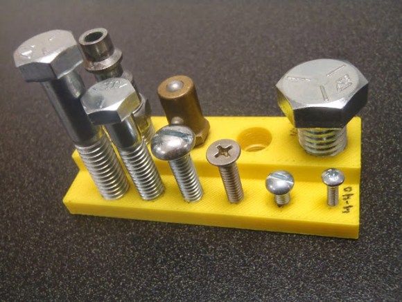
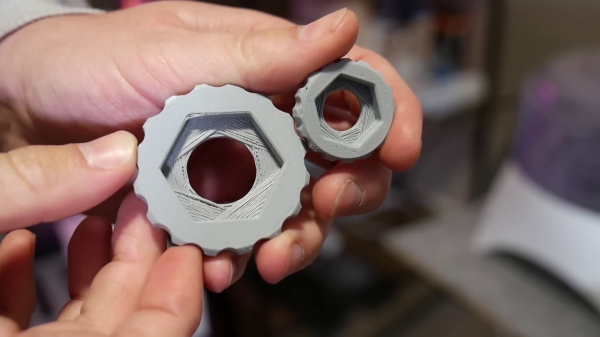
This is a common problem when you have a countersink feature for a bolt head or captured nut on the bottom of the part. [Angus] first demonstrates some other techniques, including printing the bore over empty space, adding a sacrificial bridge, and making the overhang 45°. Each of these work but have some trade-offs. The proposed solution is what [Angus] calls sequential overhangs. It involves bridging the sides of the open space in steps to create supporting edges onto which the bore perimeter can print. It starts with 2 or 3 bridging layers to create a rectangle the same width as the bore, and then a second set of bridges at 90° to turn the opening into a square. For smaller holes this should create enough of a support to start the bore perimeter, but for larger holes three sets of bridges at 60° offsets might be needed.

[Angus] does not claim to have invented the technique but states he borrowed the idea from parts printed by Prusa Research for their popular line of 3D printers. One of the comments on the [Maker’s Muse] video referenced a 2014 blog post by [nophead] showing the same approach. Regardless of the idea’s lineage, it’s a great addition to anyone’s 3D printing design toolbox.
Continue reading “3D Printing Bores Without Support”

Dynamic Build Platforms For 3D Printers Remove Supports And Save Material

We’re all too familiar with the 3D printing post-processing step of removing supports, and lamenting the waste of plastic on yet another dwindling reel of filament. When the material is expensive NinjaFlex or exotic bio-printers, printing support is downright painful. A group at USC has come up with a novel way of significantly reducing the amount of material that’s 3D printed by raising portions of the bed over time, and it makes us wonder why a simpler version isn’t done regularly.

In the USC version, the bed has a bunch of square flat metal pieces, with a metal tube underneath each. The length of the tube determines the eventual height of that square. Before the print is made, the bed is prepared by inserting the appropriate length tubes in the correct squares. Then, during the print, a single motor pushes a platform up, and based on the height of the pin, that portion of the bed raises appropriately, then stops at the right height.

This is a significant savings over having a matrix of linear motors or servos to control each square, at the cost of having to prepare the pins for each print.

But it has us wondering; since CURA and other slicing software have the ability to pause at height, what if the slicing software could allow for the placement of spacer blocks of a known size? The user would have a variety of reusable spacer blocks, and position them in the software, and the slicer would build the support material starting on top of the block. It could print a rectangle on the base layer to aid in proper placement of the blocks during printing, and pause at the correct heights to let the user insert the blocks. At the end of the print a lot less support material has been used.

For situations where you want to leave your print to run unattended, or if the cost of the material is low enough that it doesn’t justify the effort, then maybe this isn’t worth it. Another problem might be heating that platform, though since only support material will be printed on it, some curling won’t matter much. What do you think?

Continue reading “Dynamic Build Platforms For 3D Printers Remove Supports And Save Material”

Single Motor, Single Piece 3D Printed Hovercraft

RC hovercrafts offer all sorts of design options which make them interesting projects to explore. There are dual-motor ones where one motor provides lift while the other does the thrust. For steering, the thrust motor can swivel or you can place a rudder behind it. And there are single-motor ones where one motor does all the work. In that case, the airflow from the motor blades has to be redirected to under the hovercraft somehow, while also being vectored out the back and steered.

[Tom Stanton] decided to make a single-motor hovercraft using only a single 3D printed piece for the main structure. His goals were to keep it as simple as possible, lightweight, and inexpensive. Some of the air from the blades is directed via ducting printed into the structure to the underside while the remainder flows backward past a steering rudder. He even managed to share a bolt between the rudder’s servo and the motor mount. Another goal was to need no support structure for the printing, though he did get some stringing which he cleaned up easily by blasting them with a heat gun.

From initial testing, he found that it didn’t steer well. He suspected the rudder wasn’t redirecting the air to enough of a sideways angle. The solution he came up with was pretty ingenious, switching to a wedge-shaped rudder. In the video below he gives a the side-by-side comparison of the two rudders which shows a huge difference in the angle at which the air should be redirected, and further testing proved that it now steered great.

Another issue he attacks in the video below was a tendency for the hovercraft to dip to one side. He solves this with some iterative changes to the skirt, but we’ll leave it to you to watch the video for the details. The ease of assembly and the figure-eight drift course he demonstrates at the end shows that he succeeded wonderfully with his design goals.

Continue reading “Single Motor, Single Piece 3D Printed Hovercraft”

3D Printed Cookie Molds For The Best Speculoos

Experiencing nostalgia for the outstanding Belgian cuisine [Adam], currently stuck in Ohio, found himself in craving some home-made speculoos. For the uninitiated, speculoos is what those brown cookies usually served with coffee on planes dream of becoming one day.

To add some extra regional flavour, [Adam] decided to print his own molds featuring motifs from Brussels. The risks of 3D prints in the kitchen are the subject of a lively discussion. They are addressed in this project by recommending the use of food safe filament and sealant for the molds. The fact that the dough will be removed from the molds almost instantly and that the molds don’t go into the oven puts the risks in the vicinity of using plastic cutting boards in your kitchen.

[Adam]’s write up features solid, well illustrated baking instructions that should enable any of you to replicate this delicacy. Some links to additional references and two recipes are thrown in for good measure. The article finishes with detailed instructions for designing your own molds that take the properties of the medium into account, to ensure your custom motif will still be recognizable after baking. Line art with a stroke width of around 2-3 mm seems to work best. It is that time of year and we hope to see a lot more tricks to take your cookie and edible house designs to the next level so don’t forget to send in a tip.

With 3D printed molds having been used to shape resin, silicone and even metal, we are at a point where cookie dough looks like a natural progression.

Fastening 3D Printed Parts

PC100358

Ever been curious on how to fasten 3D printed parts together? There are lots of ways to do it — but what’s the best way? [Chris Lopez] works in a machine shop and decided to do some testing of how best to tap 3D printed parts, so you don’t have to!

The typical ways to add fasteners in 3D printed parts include designing the thread right into the part (only works for big threads), adding a press-fit insert, drilling and tapping it like any other material, inserting a Heli-Coil, or even by using ultrasonic weld inserts. In fact, this Stratasys blog post actually goes into some good detail on the pros and cons of each!

But, there’s a much easier way. To tap a hole normally you need to locate it accurately, make a pilot hole with a center drill — ensuring it is straight and true — then drill through with the undersized tap drill, and finally, thread it with a tap. Luckily, your 3D printer takes care of almost all these steps. By simply designing your holes to be the tap drill size you can hand tap fairly strong threads in your 3D printed parts. Just make sure your wall thicknesses and or infill settings are high enough to make sure there is material to engage!

[Chris] also goes into some detail on creating captive nut geometry — but for that you’re going to have to check out his blog. And if you’re interested in another style of fastening 3D printed parts, why not inset magnets into them while they are printing?