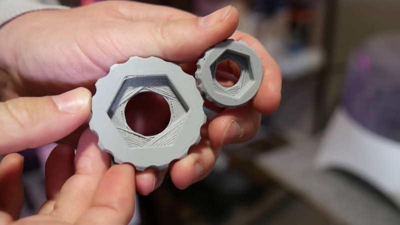
If you’ve done even a small amount of 3D printing, you probably ran into the challenge of printing a small hole on top of a larger hole. The conventional solution is just to add support, but in the video after the break, [Angus] of Maker’s Muse demonstrates an alternative solution you can implement in CAD, without having to do manual post-processing.
This is a common problem when you have a countersink feature for a bolt head or captured nut on the bottom of the part. [Angus] first demonstrates some other techniques, including printing the bore over empty space, adding a sacrificial bridge, and making the overhang 45°. Each of these work but have some trade-offs. The proposed solution is what [Angus] calls sequential overhangs. It involves bridging the sides of the open space in steps to create supporting edges onto which the bore perimeter can print. It starts with 2 or 3 bridging layers to create a rectangle the same width as the bore, and then a second set of bridges at 90° to turn the opening into a square. For smaller holes this should create enough of a support to start the bore perimeter, but for larger holes three sets of bridges at 60° offsets might be needed.
[Angus] does not claim to have invented the technique but states he borrowed the idea from parts printed by Prusa Research for their popular line of 3D printers. One of the comments on the [Maker’s Muse] video referenced a 2014 blog post by [nophead] showing the same approach. Regardless of the idea’s lineage, it’s a great addition to anyone’s 3D printing design toolbox.


I just use a fillet for this.
Much quicker to do.
How so? , what part would you fillet? Need a good solution aswell so im intrigued but not quite following you
This idea is really clever idea, kudos to whoever came up with it.
But I wish someone showed an easy way to automate it in Fusion, Onshape and other CAD tools. It’s really tedious to do by hand.
I only use it in OpenSCAD where I’ve coded up some reusable functions.
Perhaps it would be even better if slicers could do it, as then you don’t need to build in assumptions about the layer height into the model.
Not sure about other CAD packages as I’m a FreeCAD user, but this should work.
1/ Create a file with the inverse shape with an LCS centered over the sholder, either parametric or a set for different sizes.
2/ Draw your part with just the holes you want, add an LCS in the hole at the appropriate depth, import your inverse, attach and do a boolean subtract.
That way you only draw the tricky bit once and can reuse it as many times as you need. Hopefully this makes sense as I can easily envision it, but not sure I’ve described it very well.
I’ve never had an issue. Supports work fine for me. I’ve done countersunk nuts and through holes for 1/4-20’s through #4’s, 6mm, and even a few 5/8-16’s.
But the goal is to not use any supports.
Counterbore != Countersink.
This technique needs to be more widely known. Open source/hardware doesn’t live up to its potential when we have silos of information.
Here, people were given information, but they didn’t pay attention and are confused.
I read headline as “3D printing bores” and assumed it was talking about me
I simply print with my bore facing up, judging by the pic in this article it would be simple, just flip the model over. If you cannot flip the model, a chamfered edge will work(and even better if you have a flat head screw to replace), or a fillet like the other said. I have an extremely modded ender 3 pro and a dual extrusion ultimaker s3 so this is not a problem for me if I have to do it but I did learn these workarounds before the dual extruder came along.
The video was an example but an actual part that cannot change direction, which he clearly explains in the video. He also explains the cons of using a chamfer…
The original mende90 files have this for the nuttraps on the x ends….but slightly different.
Just make a layer which is ~1 or 2 layer heights. Then it can bridge easy and you just cut it out.
When I have done it in the past I have also planned it based on what layer height I plan on using and set the distance so it hits at an “exact” layer.
Hasn’t this been on prusas for a long time? At least that’s where I learned it.