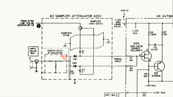
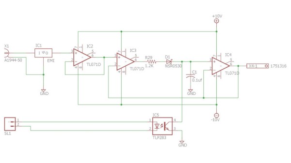
Making an oscilloscope is relatively easy, while making a very fast oscilloscope is hard. There’s a trick that converts a mundane instrument into a very fast one, it’s been around since the 1950s, and [CuriousMarc] has a video explaining it with an instrument from the 1960s. The diode sampler is the electronic equivalent of a stroboscope, capturing parts of multiple cycle of a waveform to give a much-slowed-down representation of it on the screen. How it works is both extremely simple, and also exceptionally clever as some genius-level high-speed tricks are used to push it to the limit. We’ve put the video below the break.
[Marc] has a Keysight 100 MHz ‘scope and the sampler allows him to use it to show 4 GHz. Inside the instrument is a pair of sample-and-hold circuits using fast diodes as RF switches, triggered by very low-rise-time short pulses. Clever tricks abound, such as using the diode pair to cancel out pulse leakage finding its way back to the source. To complete this black magic, an RF-tuned stub is utilized to help filter the pulses and further remove slower components.
It’s slightly amusing to note that the Keysight 100 MHz ‘scope is now “slow” while the early sampling ‘scopes had their “fast” capabilities in that range. The same technique is still used today, in fact, you probably have one on your bench.
The sampler he’s showing us is an accessory for another instrument we’ve previously shown you his work with.
Continue reading “The Magic Of A Diode Sampler To Increase Oscilloscope Bandwidth”


