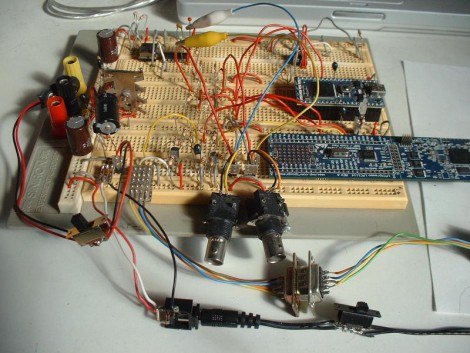
If you’ve got an ARM development board gathering dust in the corner of your shop, perhaps you could repurpose it as an oscilloscope. [Arend-Paul Spijkerman] was able to use an mbed and LPCXpresso as the hardware end of an oscilloscope. He didn’t use a standalone screen as a display, instead opting to push the scope readings from the hardware to a computer for display. This was greatly simplified by using StampDock as a basis for the GUI.
His circuit diagrams calls for an RS-232 connection for the LPCXpresso but not for the mbed. We’re not quite familiar enough with the mbed to know why, but perhaps those in the know can clue us in by leaving a comment. The probe connections are quite simple, each made up of a voltage divider and a pair of diodes. But the breadboard above looks much busier because it has two oscilloscope circuits built on it, and there’s a 10 MHz clock and a 4040 ripple counter which were used to provide a test signal.


