Measuring Frequency Response With An RTL-SDR Dongle And A Diode

[Hans] wanted to see the frequency response of a bandpass filter but didn’t have a lot of test equipment. Using an RTL-SDR dongle, some software and a quickly made noise generator, he still managed to get a rough idea of the filter’s characteristics.

How did he do it? He ‘simply’ measured his noise generator frequency characteristics with and without the bandpass filter connected to its output and then subtracted one curve with the other. As you can see in the diagram above, the noise generator is based around a zener diode operating at the reverse breakdown voltage. DC blocking is then done with a simple capacitor.

Given that a standard RTL-SDR dongle can only sample a 2-3MHz wide spectrum gap at a time, [Hans] used rtlsdr-scanner to sweep his region of interest. In his write-up, he also did a great job at describing the limitations of such an approach: for example, the dynamic range of the ADC is only 48dB.

Designing And Building A Bench Supply

[Scott’s] been digging around the back issues of the Internet to find this project. He blew the dust off and sent us a link to an article that traverses the design and build process of a bench power supply.

[Guido Socher] does an excellent job of presenting his bench supply project. So many others show of the final product, but he has gone out of his way to make sure we understand the design principles that went into it. He starts off by talking about the simplest possible supply design: a transistor and Zener diode which generates a reference voltage. He goes on to discuss the problems with this simplified circuit and how to address them, covering the gotchas that pop up at each step in the process.

Once he designed the circuit and laid out some boards he began building an enclosure. We love his tip about using a stick pin and an unpopulated through-hole PCB to mark button locations on the front bezel of the case. The final design is shown above, and includes a laptop brick to translate mains power into a 24V 3A DC feed for his custom circuitry.

Serial Port JTAG Programmer

If you’re planning to do some hacking with CPLD or FPGA chips you’ll need a way to program them. JTAG is one of the options and here’s a cheap method that uses the serial port (translated).

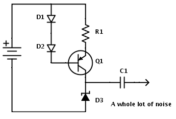
This method requires only four signals (TDI, TMS, TCK and TDO) plus ground. But the problem is that an RS232 serial port operates with 12V logic levels and the JTAG side of the programmer needs to operate with the logic levels native to the device you’re programming. Commercial programmers use a level convert IC to take care of this for you, but that doesn’t mesh with the cheap goal of this project. Instead, [Nicholas] uses Zener diodes and voltage dividers to make the conversion. There is also an LED for each data signal to give some feedback if you’re having trouble.

You can use this along with a programming application that [Nicholas] whipped up using Visual Studio. It works well via the serial port, but he did try programming with a USB-to-Serial dongle. He found that this method slows the process down to an unbearable 5-minutes. Take a look, maybe you can help to get that sloth-like programming up to a manageable speed.

[Thanks Alex]