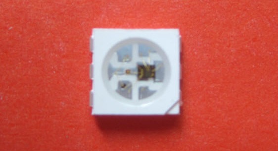
[Alan] has been working on driving this WS2811 LED module with an AVR microcontroller. It may look like a standard six-pin RGB LED but it actually contains both an LED module and a microcontroller to drive it. This makes it a very intriguing part. It’s not entirely simple to send commands to the module as the timing must be very precise. But once the communication has happened, the LED will remain the same color and intensity until you tell it otherwise. You can buy them attached to flexible strips, which can be cut down to as few as one module per segment. The one thing we haven’t figure out from our short look at the hardware is how each pixel is addressed. We think the color value cascades down the data line as new values are introduced, but we could be wrong. Feel free to discuss that in the comments.
The project focuses on whether or not it’s even possible to drive one of these pixels with a 16MHz AVR chip. They use single-wire communications at 800 kHz and this really puts a lot of demand on the microcontroller. He does manage to pull it off, but it requires careful crafting in assembly to achieve his timing constraints. You can see a quick clip of the LEDs fading between colors after the break.


If those are anything like the WS2801 ones, a good place to start understanding (for beginners, like me) them would be the “adalight” project at http://learn.adafruit.com/adalight-diy-ambient-tv-lighting. Those chips indeed handle data by removing color data and sending the remaining data down to next led.
You reset the chain by keeping the input low for around 50usec (less will usually work as well), then start sending 24-bit RGB sequences in a continuous stream. The first LED in the chain displays the first RGB value to be sent and passes the rest along the chain, the second displays the second value and so on. I’ll clarify the blog post :-)
I have a similar driver (though not in such a small packahge) on a string of LEDs. I’ve got an original MSP430 launchpad driving the string using only the hardware USI, which means I have plenty of code space and timers left to write the application. The application is my own Christmas tree lights:
http://xrobots.co.uk/forum/viewtopic.php?f=8&t=101
PS. Did a double take on that, as my first name is also Alan.
I’d use an Xmega, where the USART can be set to 800KB/sec (8Mbaud) in “sync” mode, then driven by DMA. I’d set up a pair of DMA buffers and channels, where each one is 24 bytes containing either 0x01 (for a zero: start code plus high LSB for 250nS, remainder is 2.0uS) or 0x0f (for a one: start code plus 4 LSB is 625nS, remainder is 625nS). Set up a ping-pong arrangement between them where each DMA completion IRQ does the legwork to set up the next-next pixel’s data.
I’ll need to get me some of these LEDs and/or strips and see what I can do. A general controller should be easy enough with almost the cheapest available Xmega, the 16A4U ($2.97 q.1). That should be good for ~300 pixels long and even have USB ;-)
That’s what I was thinking, it’d have to pretty much be done by a DMA controller, or a “simple” processor couldn’t do anything else.
Same done on a MSP430 Launchpad:
http://forum.43oh.com/topic/2852-ws2811-led-controller-driver/
The *bit* rate may be 800KHz, but each bit cell is divided into 5 x 250nsec chunks and you’d have to send 10000 for a 0 bit and 11110 for a 1 bit, so the actual baud rate would need to be 4MHz. Plus you’d have to think of some way of sending 5-bit chunks of data – the ATmega USART can do that, but you still only end up with 20 cycles per bit to do the output. And there’s a almost certainly a catch – although I haven’t looked at the Xmega USART I assume it is similar to the ATmega one. Although you can set it to ‘sync’ mode it still sends start/stop bits for each byte, and they both mess the timing up and are the wrong polarity. Yeah, I already though of that approach :-)
@Alan: that’s why you set the baud rate of the Xmega USART in sync mode to *10* times (e.g. the entire byte frame) the 800KHz that the WS281x wants, and *use* the start and stop bits to your advantage. You’re right about the polarity, I got that backwards, but you can trivially fix this with the INVEN bit in PINnCTRL for the Tx pin. Inverted serial 0xfe = 1100000000 while 0xf0 is 1111100000, which comes *very* close to the ideal waveform, and if I’m reading it right using only about 1/12th of the +- range for bit timings. Heck, the start and stop bits are just fine for doing a 5x setup too. Couple this with DMA where you don’t actually have to interrupt for every single bit, and this is almost trivially doable with an Xmega.
I haven’t uses the Xmega so I can’t really comment, but on the ATmega I think you’d struggle – by the time you’ve handled the USART interrupt or polled the USART status and fetched the next bit of data you are going to be spending most of the time in there anyway, so you might as well just bit-bang it. And as the original post says, the aim was to see if this could be done on a 16MHz ATmega, not on something else.
@omegacs: I understood 3 words of that comment.
Configuring an RS232-style USART for (1 start 1 stop 0 parity) would make a total of exactly 10 (2×5) bits, so assuming a start is 1 and stop is 0, your remaining 8 bytes could be 0x80 or 0xFE, transmitted at exactly 8Mbaud. You could push this through an 74HC004 to invert if the start/stop are opposite of that.
This would probably only work if the part’s USART has at least a few bytes of buffer, or with DMA.
O/C set in free running mode. Toggle on match. Clear on TOP. Set TOP to 18 then you just have to set COMPARE to either 4 or 10 (logic 0 or 1). You have 11 clocks to get the next bit into the register. Plenty clocks left for a software shifter,
Oh – and just thinking of it. If your willing to throw a whole 74HC14 at it. There is an easy way with just a few Rs Cs and a diode to make this clocking scheme from the SPI port. No software shifter and 144 clock cycles to make your next decision.
Yes, extra hardware and SPI would be another approach, but I’m trying to keep this minimal. I’d still be interested to see a schematic for the circuit, though :-)
11 cycles? I doubt that’s enough, considering the byte order needs switching from RGB to GRB. It’s fairly easy to output a single 24-bit sequence without any jitter, but outputting a string of 24 bit RGB values with absolutely no jitter between them is significantly harder.
You’d still spend most of your time handling the serial data – with a 16MHz MCU a d bit rate of 800KHz only gives you 20 cycles per bit, no matter how you actually get them out of a pin.
Was there no heat sinking on that thing?
Nope, no heat sinking. They get slightly warm when fully on but not much more.
;800mhz bit-bang on a PIC18F@ 9.8304MHz+HSPLL
;sends data for one 24-bit pixel to the strip on PORTB,7
movlw H’FF’
call _PIXEL_LOOP
movlw H’00’
call _PIXEL_LOOP
movlw H’00’
call _PIXEL_LOOP
return
_PIXEL_LOOP
movwf temp_px
movlw H’08’
_loop_bang_bits
bsf PORTB,7
btfss temp_px,7
bcf PORTB,7
nop
nop
nop
nop
bcf PORTB,7
rlncf temp_px,f
decfsz WREG,f
goto _loop_bang_bits
return
Could 480 strips of these, each with 640 LEDs, be combined into a large, passive-matrix VGA display?
yes, at $45,000 for the LEDs alone ;-)
And this is exactly why Sony’s Crystal LED display (individual smd LEDs for subpixels) shown at CES was just a penis waving.
64 LEDs per meter @ $14/meter (price for qty 1 meter, volume discount would likely apply)
640 pixels / 64 LEDs per meter = 10 meters per scan line
480 lines * 10 meters = 4800 meters
4800 meters * $14/meter = $67,200
ymmv
>16MHz AVR chip
Or you could but 80-120MHz ARM at almost same price.
There’s kill, and then there’s overkill.
That’s the equivalent of using a Arduino Mega 2560 for something a attiny-85 could handle
The Minimus cost me £3.00 each, I’m not sure anything else is going to approach that price point.
I’ve got a strip of these, I’m driving them with an ATtiny85@8mHz, no problem. It takes all the CPU time though. You could do it with hardware SPI but I’m not sure you’d gain much because you’ll get an interrupt every 2uS or so… it probably needs *more* clock cycles in the long run to do it that way on an AVR chip.
Tried ramping it up to 16mhz (or even better, 20)?
Or is it the low voltage version capped at 10mhz you’re using?
8MHz? That’s 2 cycles for the 250nsec pulses, which seems unbelievably tight.
Alan, thanks for your inspiring post. Doing this at 8Mhz _is possible_. I think I’ve succeeded in doing this; I’ve got the code working for my led strips and my calculations tell me that every bit should be exactly 1250ns for my code. I don’t have a good enough scope to validate the timing. My source code and an explanation how it’s done is at http://rurandom.org/justintime/index.php?title=Controlling_WS2811_led_strings_at_800kbit/s_without_external_oscillator
So are they 2811 or 2801 ?
Can’t find anything on 2811
Set the tiny85 for 20MHZ Fungus
These are WS2811, the WS2801 is not the same thing. See the links on the original blog post.
very cool, didn’t know these “LEDs”. I ordered 500 pieces to play with :)
What vendor did you buy from?
I got mine from http://www.clenled.com/en/
The FastSPI library can already talk to these LEDs. It’s the same as the tm1809 timing.
Yeah – FastSPI_LED? Works great!
http://code.google.com/p/fastspi/
I’ve been contacted by some folks who say that FastLED doesn’t work for them whereas my code does. The FastSPI timings are out-of-spec so it probably depends on the batch of LEDs you get as to whether they work or not with FastSPI. I’ve put an update at the bottom of my blog post with details.
It would stand to reason these are the same as the WS2901 driver IC — shift 24 bits and wait 50us to set the latch. Led stays at set colour until more valid data is latched.
[youtube http://www.youtube.com/watch?v=tWjcMlhfz1Y&w=560&h=315%5D
Same principle, but the WS2811 is 3 wire, not 4 – it has Pwr, Gnd and Data, but no Clock. The timing of a pulse indicates whether the bit is a 1 or 0. Roughly:
-___ is a 0
–__ is a 1
There are 2 speeds at which the device can operate, but I’m not sure how it detects which speed you’re using.
The speed is set by pulling a pin on the IC to low or not,m these LEDS don’t have the pin connected
WS2901 doesn’t exist, and no, these are not the same as WS2801 at all. WS2801 is 2 wire, 2811 are 1 wire.
That’s not the way they work. The >= 50usec reset is at the start of the sequence, then you have to send a continuous stream of 24-bit BGR values with no delay between them. It’s explained in the datasheet and in my blog post.
Great post, Alan. Well done on the fine tuning of the assembler code to get the timings just so. I am also playing with WS2811 – got a bunch pre-mounted on tape via Aliexpress. Initially, just for playing around I got one of the cheap multi-chip controller boxes from China, but I’m planning on using a PIC32 – surprisingly cheap for the amount of flash and RAM that’s inside, and I need to get back in to microcontrollers (it’s been about 15 years since I last played with them)
Hi maybe here ill get an answer….
I bought a ws2811 led strip with sixty led per meter which has only 3 cables. V+ v- and data.
I’ve also ordered a few controllers from alibaba – the first one worked on dmx control and connecting only the data wire was enough to control each pixel individually through dmx.
After that I tried using a video controller after fighting with supplier to get some sort of manual and connecting the data output to the strip doesn’t seem to respond…
Can anyone help?
Hi alan
I search detail of ws2811 to interface with AVR and every where I found your referencel only and your article link only but when I try to open link is expired.
Can you please sent me pdf or fresh link of your article to learn and understand ws2811 and its interface.
Thanks