3D Printering: the final frontier. These are the voyages of another 3D printer hack. Its mission: to explore strange new ways of leveling a print bed.
So far, we’ve had servo probes, Allen key probes, Z-sled probes, inductive and capacitive contactless switches, just to name a few. All of them allow a 3D printer to probe its print bed, calculate a correction plane or mesh, and compensate for its own inherent, time variant, inaccuracies.


These sensors are typically mounted somewhere on the print head and introduce their own sensor offset, which has to be precisely calibrated for the whole thing to work. To eliminate these offsets – and a large part of costly EOL testing and calibration – the Polish 3D printer manufacturer Zortrax uses a smarter approach: Conductive pads on the build plate. During the leveling procedure, the printing nozzle makes contact with these pads, which practically turns the nozzle itself into the probe — offset-free. Makerbot patented a contact sensing solution based on force sensors located in the print head, although similar builds based on limit switches were known before. Other DIY builds use force sensitive resistors (FSR) underneath the build plate to achieve the same. All these techniques are based on the detection of a brief contact between the printing nozzle and the build plate, and are therefore offset-free.
Compelled by the idea of eliminating the last manual calibration step, I wanted to make Zortrax’s method of contact sensing compatible with non-conductive PEI, Garolite and glass build plates. I didn’t want to interfere with the Makerbot patent, and force sensitive resistors would not survive the temperatures of a heated bed. I figured that I could just strap a sufficiently heat resistant piezo sensor to the print bed to sense the little knock the nozzle would make when it collides with the print bed. However, not much sound energy is released when a nozzle runs into a build plate at blazing 1 mm/s. A first test revealed that the knocking sound was too weak to be reliably distinguished from other vibrations in the machine.


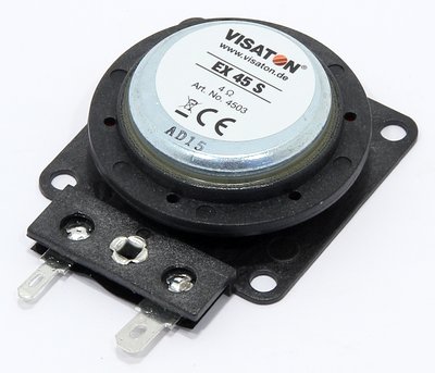
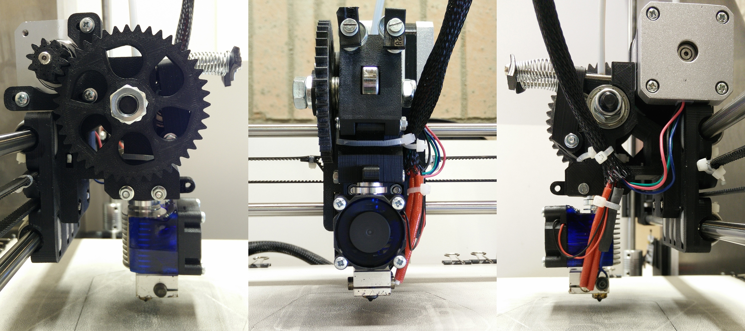
To fix this, I acquired a 10 W structure-borne sound exciter and attached it to the extruder. The exciter allowed me to actively inject a white noise signal into the nozzle. If it was strong enough, this signal would travel through the entire printer and could be picked up by the piezo discs in the print bed, far above the printer’s own noise level. I assumed, that when the nozzle touches the print bed, the transfer function between the exciter and the piezo sensor must change rapidly due to the direct transfer of sound between the two. This change would then lead to a rapid change in the amplitude spectrum the piezo picks up. A little DSP could process the piezo signal, detect these rapid changes in the amplitude spectrum and give back a trigger signal to indicate the collision.
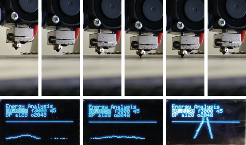
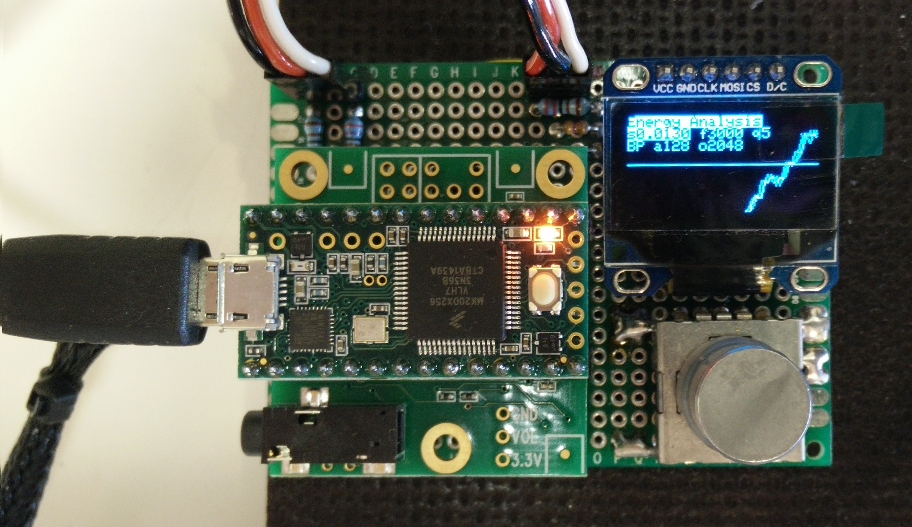
For the required realtime DSP, I hooked up the piezo discs to a plain Teensy Audio Shield equipped with a Teensy 3.1, which practically completed the hardware portion of this project in one step. Using Paul Stoffregen’s amazing DSP library, it took only a few lines of code to run a 256 point FFT on the input signal and a few more to generate a time-averaged amplitude spectrum. The little sketch compares this averaged “frequency fingerprint” of commonly present vibrations to the current spectrum, calculates an overall energy difference between the two, and if that difference exceeds a certain threshold, the Teensy pulls an output pin low, telling the 3D printer controller that the nozzle just touched the build plate. I later added an OLED display and rotary encoder, basically for plotting the signals and for being able to adjust the threshold.
This turned out to work quite well, while submersing the whole printer in a pleasant swoosh noise, but it added quite a bit of additional weight the extruder assembly. Also, these exciters aren’t particularly cheap, and an additional audio amp would be required, too. It wasn’t really it.
It took a while for me to figure out what I would do with the whole project. And then, just when I was about to send it into project-limbo, I had another idea: To save cost and weight, I could use the extruder’s stepper motor as the exciter, the stepper motor driver as the amplifier, and stick with the cheap piezo discs attached to the print bed as microphones. In theory, the 3D printer controller could both generate the noise signal and process the sound signal from the piezos, so the only additional component would be the preamp and the piezo discs.
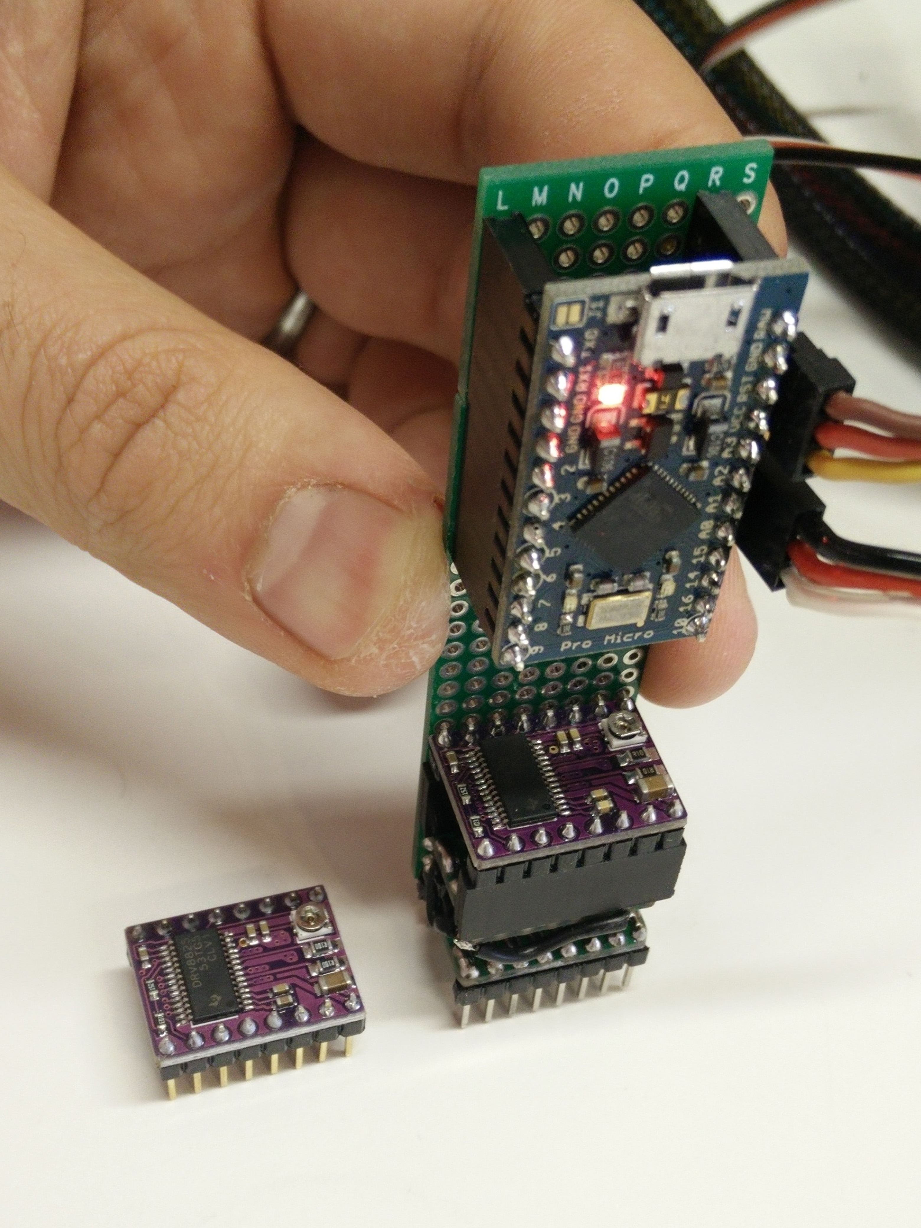
Yet, it was still unclear if the stepper motor would adapt to become some sort of speaker, so that’s the first thing that needed testing. I hacked together a little noise injector board that would go between the 3D printer controller and the stepper driver. This little hack utilizes an Arduino Pro Mini clone to switch between two modes: A bypass-mode, where it just passes through the signals from the 3D printer controller, and a noise mode, where it streams a pseudo-random sequence of forward and backward micro steps to the motor driver. This, I hoped, would cause the stepper motor to oscillate and produce a noise signal. And well, it did. I turned it on and the extruder motor swooshed with a strong noise, very similar to the exciter I used before, although the extruder’s gears rattled quite a bit.
I tweaked the random sequence to make sure that the stepper motor would never perform an actual full step as a random accumulation of micro steps. Besides that, everything worked surprisingly well. The probing is accurate to a level where it becomes really hard to tell how accurate it actually is. If the nozzle touches down to a sheet of paper and stops once it senses the touch, the paper will slide easily and consistently between the nozzle and the build plate without being stuck. Since then I’ve been using this for several prints, and it works just like regular auto bed leveling probes, although with fewer advantages than expected: It eliminates the offset calibration, but also introduces a threshold value for the touch detection.
From an economical view, this is still a nightmare. On current Arduino-style 3D printer platforms, it takes an additional DSP, DAC, a preamp and the noise injection adaptor to implement this sort of sonic auto bed leveling. Even if the piezo discs are virtually free, everything adds up to about 5 times the cost of a decent capacitive distance switch.
It might make more sense in the not so distant future. We’re beginning to see a new generation of 3D printer controllers that feature a more powerful 32 bit MCU, ideally we want one that supports DSP instructions. Given the availability of cheap STM Nucleo boards with powerful, DSP-enabled ARM Cortex-M4 MCUs, my bet is that insanely powerful 3D printer controller electronics, capable of tricks like this one, are bound to happen rather soon. For now, enjoy the following video of an early test of the sonic auto bed leveling:


Could you float the plate on a liquid? : )
That would get it level, but not necessarily perpendicular to the z-axis…
Toss in a Hydraulic z axis?
Float the Axis too… :D
Could work. Continuity probe on the print head to find the surface of the liquid. I am not sure how precise this would be though.
You could make the entire printer out of clear plastic and glass. Then use light instead of sound. :D
Yea, you could float the plate on a sea melted gallium. When you want to level it, heat up the gallium until it melts (29.76 degrees Celsius) Let it float level and then let the gallium cool and harden. You are now level with a solid foundation. The next challenge is keeping the heated bed from melting the gallium again. Not too useful since this does not compensate for irregularities in the building surface, levelness of the xyz motion system, and simply being at the right level. Its good to brainstorm, though.
analog band pass filter tuned to the frequency of the oscillation of the extruder. If we can play music on an extruder we can have a band pass that picks up only that one note and triggers…you might even be able to do it with a single cheap op-amp…digital isn’t always the solution – although it can usually be an answer.
I’d love to see a purely analog implementation of this. Although an oscillation of only a single frequency transmits very few energy compared to white noise. Also, they create standing wave nodes on the plate, so it would be quite an effort to get a uniform sensitivity across the entire build plate.
Wouldn’t the greatest signal strength would be at the resonant frequency of the piezo, so why not use a piezo mounted to the heatsink fins on the hotend as the exciter? Physical contact of the nozzle would increase the received amplitude greatly, no?
If you were concerned about standing waves at a single frequency, surely an array of piezos as you have on the bed would be able to detect this. The Arduino Knock sketch has a principle of reading the voltage when piezo is touched (vibrated at resonant frequency in this case) and a high value resistor is between the piezo terminals. Could this be the basis for a digital input to the controller, perhaps with op amp? With ATMEGA/RAMPS/MARLIN, you could use a pin to enable the sound excitation (custom G/M code required?) and just link the piezo array input to the probe pin.
The haptic motors would also be a good approach, as already suggested, if you didn’t want to use highly audible frequencies but I wonder if the amplitude of the bed during vibration would make this low frequency imprecise.
Finally, any thoughts on whether the response of an electret microphone would make them suitable? What’s the leap in detectable signal between an air gap and physically touching? Would they work over a greater range of frequencies?
where is the swoosh? are you trying to make a nike logo or is it the noise of the sonics?
You’re eventually going to chew up your Z-axis mechanism this way.
Why not excite the bed with a broadband acoustic signal, and look for the impedance change when the print head contacts it?
That was my initial thought as well. Vibrate the bed, and sense a change in sound when the nozzle comes in contact.
VERY original idea, design and implementation. Congratulations!
As an aside, Zortrax patented the conductive bed pads approach. I think it’s a BS patent but it’s still a patent. If you’re just doing it for yourself you’re reasonably safe (if still technically violating modern patent laws, but probably too low profile to be a concern to them), but if you want to sell the parts or the machines to do this, you might run into trouble.
One of the ways to avoid z-wobble is avoid over constraining the screws, several designs use isolators that “float” the X gantry, so the method in this article won’t work for them.
In any case, it pretty much sucks for a 3d-printer anyway. The nozzle coats itself in non-conductive plastic *by design*, so getting a reliable electrical contact is a non starter.
Can you use the Thue-Morse Sequence for injecting the white noise?
https://www.youtube.com/watch?v=prh72BLNjIk
Use a small vibration motor to create the noise, cheap and easy to control. The amplitude is dependent on the motor speed. It should have a very distinct signature that would be easy to detect.
Mine has one already. The extruder fan =) And running constantly, no need to control.
I don’t quite get why you need the complexity of white noise. Surely you could just modify the pattern of steps the controller uses as it approaches the bed, in a Up-Down-Up-Down-Up-Down-Down kind of way so that when it reaches the critical height it’s tapping the bed like a woodpecker at high speed. What’s with the white noise requirement?
Yeah, I tried the woodpecker tapping. It works better at high speeds, but the accuracy is terrible. You really need to smash the nozzle into the build plate to get a well-defined transient signal that lies above the general noise level. White noise transmits the maximum energy within a given bandwidth and also isn’t affected by standing wave nodes in the build plate.
Another posibility: Just send steps at a rate that’s too high for the stepper (e.g. x khz * microsteps) after making sure it’s definitely not moving (no steps for y ms). The stepper will not be able to accelerate fast enough and therefore miss steps at a certain frequency. Then, use the technique described by [restrictedayerspace] above to detect the signal.
If done properly, the stepper should vibrate less then a step, therefore limiting the amount of damage it could do to the mechanics.
Part of this, I already tested (accidentally), while working on a very basic step generator in verilog. My clock divider was not working as expected and sent step signals at about 120khz. Since I used 16 microsteps, that should be a bit more than 7 khz. The stepper was not strong anough to accelerate that fast, instead, it started whining.
*possible solution
I’ll just go join the others in the “please let us correct our comments after we sent them / spell checking? what’s that” corner…
Very cool idea & good writeup, however ‘im with’ some of the people here saying your sorta messing up your gears/belts/etc, i liked the approach with the ‘structure-borne sound exciter’ more, but understand what your saying about cost, however, what about a simple pager motor? those can be had for cheap afaik, and that should be detectable/destinguishable too
Thanks! Haven’t messed ’em up yet, but the fizz is gone. A pager motor won’t produce white noise (at least if not driven with the same trick I’m using with the stepper motor). The noise is necessary, since monofrequent oscillations carry too few energy at a given bandwidth/amplitude and also create standing wave nodes on the build plate. At these nodes, the sensitivity is practically zero.
Ah i see, thanks for the insight and good to hear the printer is fine so far :)
“structure-borne sound exciter” = fancy name for a speaker that bolts to things. Figure out a way to mount a small speaker to the extruder so it’s quick to remove for printing.
Making it detachable is a great idea. Although it’s more a fancy name for what it actually is. SBSEs don’t have membranes, instead, they have a piece of mass. A regular speaker won’t really work here.
Couldn’t you get the same effect as the Zortrax setup by just using a sheet of aluminum foil you place on the bed for levelling purposes, then take off for printing? Or better yet, combine the Zortrax system and the servo-switch system, but with a curved bit of foil instead of the switch, and the servo swings it down under the nozzle, ready to be sandwiched between the nozzle and glass.
I’ve tried the conductive pad solution once, it was alright, but not perfect. The nozzle has plastic remainings all over, and isn’t a very good conductor. This resulted in the extruder squishing the bed before making actual contact, so that the leveling would be inaccurate. This is with the extruder heated to printing temp, otherwise it isn’t working at all.
Why not move the conductive pads to a different location? Say at the Z rods/rails? When the nozzle contacts the bed, the conductive pads on the Z rails/rods open, telling the printer the nozzle is at Z0.
Seems like a defined modulated audio tone would be enough to pick out of the noise if you could strap a microphone to the bed and adjust the threshhold to cancel out the vibrations delivered through the structure. I think you would have to FFT the resulting speaker output and compare to the known tone or tones. I know I’ve seen steppers used as speakers before. (http://makezine.com/2009/06/23/stepper-motor-music/) As an added bonus it could say things like “autolevel complete” through stepper vibrations which hopefully could be more audible with the nozzle in contact with the bed. I def. don’t know how to do any of that though, so maybe I’m a bad person for suggesting anything. As long as we’re spitballing here, I think the right answer is to have a bed that is gimbled and has steppers on lead screws to level itself.
Adjusting just the bed itself doesn’t work if the bed isn’t perfectly flat. And they aren’t. Nozzle strike detection can be used in conjunction with bed mapping to account for variations in height across the bed. So, nozzle strike detection is very important.
I wish more details were given in this article. I did not notice any code posted, nor a description (or sample data) of what the input to the piezo looked like, what frequency bins were used, or how much of a change in the bins should be considered a real event. Anyone that has this information, I would greatly appreciate it if you could post.
I have tried a number of methods using piezoelectric disks including transmitted sound – from a pager vibrator motor in my case. The biggest problems I found were dead areas on the plate where standing waves cancelled out. You may also run into some problems with the limited usable temperature range with the PZT ceramics used on these disks I did find that the simple click of contact can be detected although I settled on detecting reduction of force on a set of three disks. Details of this at http://forums.reprap.org/read.php?1,635075,page=1 and http://www.thingiverse.com/thing:1399512
Mike
“Sonic 3D” is what I saw first in the title. And then I realized it has nothing to do with SEGA products. :-)
I’m glad to see someone using sound for pseudo-bed-leveling. (To me bed leveling means adjusting the bed to make it level, not measuring the nonconformity) I had no idea anyone would take it to this extreme. :-) (FFT and all) I imagined someone simply setting up a high gain amplifier between detector on head and sound source on bed (or reverse) such as to create a wicked feedback loop when touching. Then slowly lift until the feedback stops and then you’ve measured the point.
There is no need for either wicked feedback nor even high gain – 2 is close enough to “very high” with piezo transducers as long as the amplifier has a decently high input impedance – You would be amazed quite how large an output you get from a piezo disk used as a sensor.
Mike
Makes sense to me that the piezo element already has high gain built in. :-) Anyone who has ever shocked themselves on the igniter trigger on their gas water-heater knows they can be substantial. :-)
Aren’t we ignoring the transferability of the Zortrax shortcoming that people have pointed out here? If filament deposits on the nozzle below the lowest point of the metal, this sensor technique appears to be fooled into thinking that the nozzle is in contact with the bed when it is a potentially significant distance above. Yes, the relative distance between bed probing points will be unaffected but your all-important first layer might be.
Deposits on the nozzle along with particles picked up from the build stage can be a problem but there are various workarounds. Using the nozzle hot after extruding a small amount of hot filament then retracting the filament and wiping the nozzle on an unused part of the bed goes a long way. Doing a sanity check to check that the measurement is about what it should be and repeating until it looks safe should also help. The sound transmission technique should also give a better idea than force-contact measurements as there will be attenuation of higher frequencies even with a thin layer of soft extrudate.
Mike
have you tried a pager motor (boy does that date me!) or a disc motor, spinning at a rough harmonic of your piezeo pickup? orient it so that it”s effective motion is in the vertical plane..IE: shove it between the fins of the extruder heatsink :-} you should be able to provide power 1 to 3 volts, and control through your detection circuit good luck JB
It has been mentioned that white noise should be used to avoid standing waves, because if the nozzle hits right at a standing wave node, in theory it might not be detected since it is hitting the bed where it is not moving. Using multiple frequencies prevents any point from being at the middle of a standing wave for all frequencies used. I’d love to use a pure tone if this isn’t a real problem. I haven’t tested it since white noise was suggested, but a pure tone certainly simplifies things in some ways.
How have you generated a pseudo-random sequence of microsteps? I need to do similar project on university. Could you help me?
In the main loop, generate a random number (with an offset so it can’t be too low — the speaker won’t respond to frequencies under about 30Hz), and use it to play a tone. The loop repeats thousands of times per second, with a new random number each time, effectively generating white noise within a defined frequency range. For example (I am using a Teensy — I don’t know if the pinout is the same on an Arduino or other board, but just choose an analog out pin and use an amp before the speaker since these boards only output milliwatts):
============== CODE ===========
int outPin = A8;
int toneFreq;
void setup () {
}
void loop () {
toneFreq = random(1000) + 1000;
tone(outPit, toneFreq);
}
============ END CODE ==========
Note that the Teensy has white, pink and brown noise commands so you wouldn’t even have to use the random number technique, but I haven’t been able to find documentation on this for the Arduino so it may be Teensy-specific and so I avoided using those commands.
More detail from the author would be greatly appreciated. The code would probably answer many questions I have, such as what frequency range is being used for the white noise, exactly how white noise is being generated in the code, what the FFT frequency bins are, and how much of a change is considered a valid nozzle strike.
I have attempted to replicate this work, using almost the exact same hardware, and I find that the surface exciter transmits < 1V to the piezo. While the signal is detectable, I'd like a larger signal because the microcontrollers and stepper motors create a lot of interference (I'm filtering high frequency noise from the piezo with an RC filter and have it down to about 0.2V — without the filter, the noise can be +/- 1 volt). Any suggestions for dealing with this EMI would be great.
On the mechanical side, I'm wondering exactly where to mount the exciter and piezo. I can't mount the piezo directly under the bed because there is a heat mat there which can get much hotter than the piezos are rated for. I'm leaning towards epoxying some extensions to either side of the bed and putting the exciter on one side and the piezo on the other so that the main path of the sound is through the bed, not the frame, to maximize transmitted power.
And by the way, really nice work — I just wish I could get it working that well lol. Looks good too. The addition of the LCD is sweet, and that's a nice Prusa frame — where did you get it?
Caveat Emptor: I ask about where you got your frame because I ordered a Prusa i3 kit with a steel frame (P3Steel) from Orballo Printing and have yet to figure out how to assemble it (even though I've assembled a Prusa before). It came with no instructions, and a lot more 3D printed parts than my other Prusa, some of which were poorly printed. Also, I suspect some parts are just missing, though that is hard to tell for sure since I don't have instructions. I've contacted them and they don't seem interested in providing help. Very frustrating. I strongly suggest not buying from them.
May I suggest you ask the forums?
http://forums.hackaday.com
Because this article is almost a year old, most of your questions are unlikely to be seen.
Good luck! I’m slightly disappointed that there is no code as well.
Thank you for the suggestion, I will do that.
I registered and waited for the confirmation email. It did not come. I requested it to be resent twice. No luck. Hopefully their mail server is just backed up or something and it will show up eventually.
What an awsome toy :)
maybe you can share the sketch for the arduino?
The time it took to develop and implement this is more cumulative time than I will ever spend manually fiddling with knobs on the bottom of my CR-10. But it’s the best kind of clever overkill.