When the only tool you’ve got is a hammer, every problem starts to look like a nail. Similarly, while a 3D printer is a fantastic tool to have, it can make you think it’s possible to build all the things with printed parts. Knowing when to print ’em and when to machine ’em is important, a lesson that [Diffraction Limited] has taken to heart with this semi-printed silent air compressor.
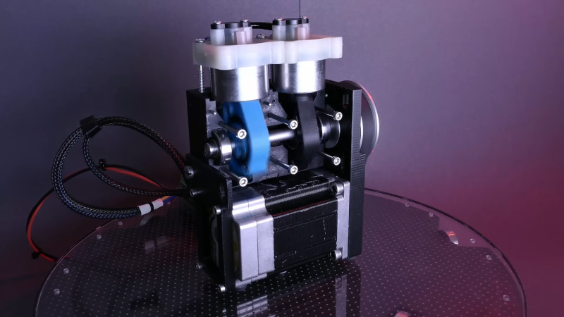
The key to this compressor’s quiet operation is a combination of its small overall size. its relatively low output, and its strategic use of plastic components, which tend to dampen vibrations. The body of the compressor and the piston arms are the largest 3D-printed parts; the design calls for keeping printed parts in compression for longer life, while the parts of the load path in tension travel through fasteners and other non-printed parts. The piston design is interesting — rather than being attached to connecting rods via wrist pins, the machined Delrin pistons are solidly attached to the piston arms. This means they have to swivel within the cylinders, which are made from short pieces of metal tubing, with piston seals designed to move up and down in grooves on the pistons to allow air to move past them. The valve bodies atop each cylinder are salvaged from another compressor.
When powered by a NEMA23-frame BLDC motor via a belt drive, the compressor is remarkably quiet; not quite silent perhaps, but still impressively smooth, and capable of 150 PSI at low speeds. And as a bonus, the split crankcase makes it easy to open up and service, or just show off how it works. We’ve seen a variety of 3D-printed compressors, from screw-type to Wankel, but this one really takes the prize for fit and finish.
Thanks for the tip, [Whye Knott] — lol.


Having the electric motor in the base should make it stable, and fits the overall size of the crankcase.
Elegant indeed.
Yeah this is pretty great.
One thing I don’t understand is how the rubber seal works. As the piston moves either down from the top or up from the bottom towards its midpoint, the rubber ring goes from being perpendicular to the cylinder axis at both ends, but tilted one direction on the up-stroke and the other on the down, and therefore has to have a larger circumference at the middle. This could be handled by having the cylinder taper inward as it approaches the midpoint from either end, but no mention was made of any machining that had to be done on the cylinders. The stroke is short enough that the angle between the seal plane and the cylinder axis is enough for this elongation to be significant. This can be seen at 2:30 in the video. Obviously it works, since if this wasn’t somehow taken into account, it would result in the seal leaking at the middle of the stroke, and this would result in a loss of pressure, and yet we see no such loss. Does the air pressure just press it against the cylinder? If so, then it is flexing and relaxing during every stroke, which seems like it would wear it out quickly.
The only thing I can imagine is that the outer wall of the cylinder is not straight but spherical.
The tilt is so small that the rubber seal compensates. The top part, seal and cylinder are from cheap commercial units. The upgrade on this unit is the reduction in speed and to compensate, doubling the capacity with the 2 pistons.
Would it be practical to ‘bend’ the cylinder so the upgoing piston is always perpendicular to the wall, but the downgoing piston opens a space mid-stroke for air intake? One would have some dead volume at the lower turning point, but on fast going compressors that may help reversing the piston.
The o-ring is not tight fit on the piston and oversized for the cylinder, it’s captive but can float along a shaft on the piston. The o-ring itself is not torus shaped but more like a car tire. This allows it to deform to fit the cylinder.
This is how most cheap oil less air compressors work.
https://www.youtube.com/watch?v=tZWJkPRnW4E
This looks like a well designed project, but it has the chicken and egg problem. buying two compressors to make one is not very efficient.
After a bit of searching, I found: “KK-4835”. With that magic word you can find a set with a replacement cylinder sleeve, piston rod and seals. But most sets do not have the cylinder head with the valves
The piston rod in this set is longer, and that may be an important factor. Because of the longer piston rod, there will be less wobble in the piston, and that may be a bit easier on the seal and cylinder walls.
And of course, there are probably replacement sets available for other compressors too.
I wonder how many pistons you could add
One of the key things that makes this design quiet is its high torque brushless dc motor and gear reduction – as the video explains, conventional air compressors depend on momentum to power through the hardest part of the compression stroke, so they need to run at a high speed or not at all. This one can run at whatever speed is necessary and it can also “soft start” rather than immediately spinning up to full RPM.
This also simplifies the design because you don’t need an unloader valve to relieve pressure every time the motor stops – it can just push against the fully pressurized cylinder instead of stalling.
I’d be curious to see how well this type of system could drive a much larger compressor, but the cost of an appropriately beefy brushless motor and controller makes it rather impractical.
The gearing will wear uneven, one should be able to rotate the gear on the crank shaft from time to time to compensate that.
Have the output shaft ratchet in the reverse direction like the back tire of a bike. Then, every time it starts up again have it reverse a few clicks.
No, the big timing belt pulley has it’s force divided over so many teeth that it will have no practical wear. The little pinion on the motor shaft may wear out, but if it’s number of teeth is a relative prime number to the big gear, then wear will be divided evenly among all teeth.
Same for the timing belt. Relative prime numbers of teeth will ensure evened out wear of the whole belt.
And if wear is really an issue, then use a bigger sized belt. The belt is a 222-2GT (@19:15), so it has 111 teeth, but 2GT may be too small for this application.
This is great design.