GPS can be a bit complex of a technology – you have to receive a signal below the noise floor, do quite a bit of math that relies on the theory of relativity, and, adding insult to injury, you also have to go outside to test it. Have you ever wondered how GPS antennas work? In particular, how do active GPS antennas get power down the same wire that they use to send signal to the receiver? Wonder not, because [Tom Verbeure] gifts us a post detailing a mod letting a fancy active GPS antenna use a higher-than-expected input voltage.
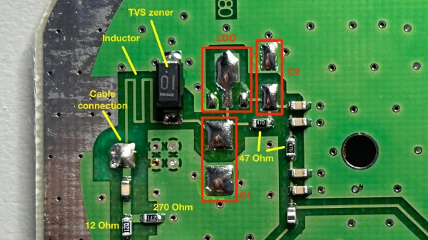
[Tom]’s post has the perfect amount of detail – enough pictures to illustrate the entire journey, and explanations to go with all of it. The specific task is modifying a Symmetricom antenna to work with a Symmetricom GPS receiver, which has a puzzling attribute of supplying 12V to the antenna instead of more common 3.3V or 5V. There’s a few possible options detailed, and [Tom] goes for the cleanest possible one – replacing the voltage regulator used inside of the antenna.
With a suitable replacement regulator installed and a protection diode replaced, the antenna no longer registers as a short circuit, and gets [Tom] a fix – you, in turn, get a stellar primer on how exactly active GPS antennas work. If your device isn’t ready to use active GPS antennas, [Tom]’s post will help you understand another GPS antenna hack we covered recently – modifying the Starlink dish to use an active antenna to avoid jamming on the frontlines.
[K5ACL], aka [SignalSearch], recently brought his active receive loop antenna in off the roof to give it a checkup and perform any necessary maintenance. While it was in the shack, he took the opportunity to discuss how well it would perform indoors. The verdict? Not ideal. He’d mount it 50 feet away from the house if the HOA would let him.
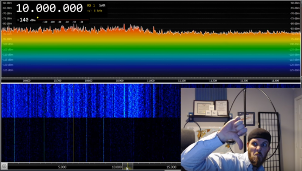
Houses, and subsequently most ham shacks, are filled with noise sources that interfere badly with HF. So after spending a minute or so listening on an SDR, [K5ACL] demonstrates another use for this type of tightly-tuned antenna—as a noise detector.
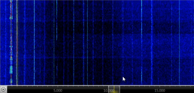
The main culprit in [K5ACL]’s house is the ceiling light that’s right there in the shack. You can see the noise striping the waterfall as he turns it on and off. But the noise from the light is small potatoes compared to some other common household items, like those power line adapters that turn house wiring into networking cable. Those produce so much noise that even an active loop is really no match. Stay tuned after the break to watch [K5ACL] work the bands through the noise.
Loop antennas are great if you’re stuck in an apartment building or a congested city. They’re easy enough to make, whether you want a portable loop or a permanent installation.
If your hobby is chasing radiosondes across vast stretches of open country, and if you get good enough at it, you’ll eventually end up with a collection of the telemetry packages that once went up on weather balloons to record the conditions aloft. Once you’ve torn one or two down though, the novelty must wear off, which is where this radiosonde conversion to an active L-band antenna comes from.
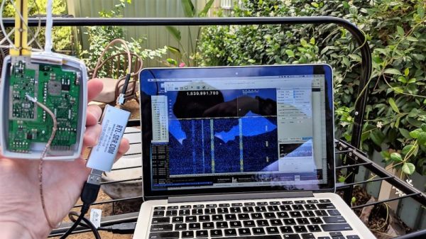
As it happens, we recently discussed the details of radiosondes, so if you need a primer on these devices, check that out. But as Australian ham [Mark (VK5QI)] explains, radiosondes are a suite of weather instruments crammed into a lightweight package with a GPS receiver and a small transmitter. Lofted beneath a weather balloon into the stratosphere, a radiosonde transmits a wealth of data back to the ground before returning on a parachute after the balloon bursts. [Mark] had his eyes on the nice quadrifilar helical antenna used by the Vaisla R92 radiosonde’s GPS receiver, with the aim of repurposing them. He had a lot of components to remove while still retaining the low-noise amplifier (LNA), but in the end managed to get a working antenna with 40 dB gain in the L-band, and with the help of an RTL-SDR dongle he picked up solid signals from Iridium satellites.
Want to score your own radiosonde to play with? First, you have to know how to listen in so you can find them. Or, you know – there’s always eBay.
If you need to generate a radio frequency electrical signal, you will make some form of electronic oscillator. We’ll probably all be used to oscillators using transistors, tubes, logic gates or a host of other electronic technologies. Similarly if you need to generate radio frequencies at high powers, you’ll couple your oscillator to an amplifier, a relatively simple task with today’s electronic parts bin.
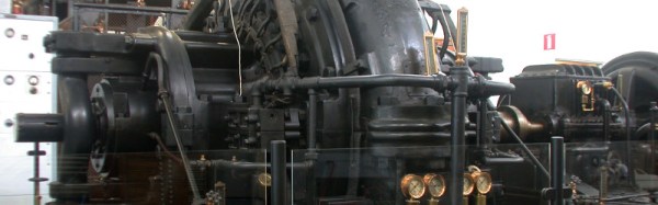
If you needed to do the same thing with a high power radio signal in the early years of the 20th century, none of these options were open to you. There were no transistors or integrated circuits, and the tubes of the day could not produce high power outputs. Radio engineers back then had to employ other solutions to the problem, one of which was the Alexanderson alternator. It’s old news we’ve covered here before at Hackaday, a high frequency alternator capable of generating hundreds of kilowatts in the VLF radio frequency range.
There is one operational Alexanderson alternator remaining in the world at the Varberg radio station at Grimeton in Sweden. It is no longer in constant use, but as a World Heritage Site and museum it is put on air a few times a year including the Sunday closest to the 2nd of July, known as Alexanderson Day. We come now to the point of this article: this year’s 3rd of July Alexanderson Day transmission is fast approaching, and since last time we covered it we signed off with a plea for a good VLF antenna design we should post a solution in good time to allow our readers to receive this year’s signal.
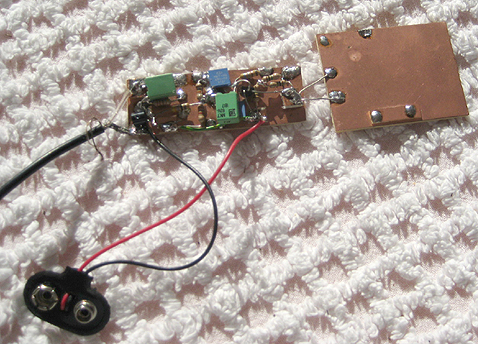
Fixing up a receiver is easy enough, we linked to the original SAQrx VLF Receiver and the extended version in our previous coverage. Both pieces of software use your computer’s sound card as the front end of a software defined radio to receive the 17.2kHz from Grimeton. The antenna though presents a problem. You might think that attaching a long piece of wire to the microphone input would be enough, but the problem is that due to the huge wavelength of the VLF signal any reasonable long wire you might be able to assemble simply wouldn’t be long enough to deliver a good result. Clearly a different antenna is required, and the solution comes courtesy of a high-impedance active e-field antenna. This uses a FET input and a surprisingly small patch antenna to deliver a low noise floor at VLF frequencies rather than to be the amplifier you might expect.
If you build either of these antennas we hope you’ll be able to hear the Alexanderson Day transmission. The point of a high power VLF transmitter is that it has a huge coverage area, so it should be possible to receive it across all of Europe and perhaps into the eastern United States. If you are out of range though, never fear. You can always try to pick it up through a handy webSDR receiver closer to the source.
Alexanderson alternator picture By Gunther Tschuch (Own work) [ CC BY 2.5 ], via Wikimedia Commons.