Talking Head Teaches Laplace Transform

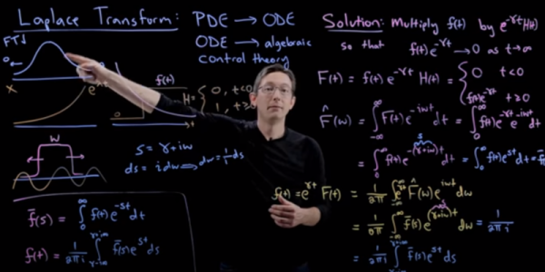
Most people who deal with electronics have heard of the Fourier transform. That mathematical process makes it possible for computers to analyze sound, video, and it also offers critical math insights for tasks ranging from pattern matching to frequency synthesis. The Laplace transform is less familiar, even though it is a generalization of the Fourier transform. [Steve Bruntun] has a good explanation of the math behind the Laplace transform in a recent video that you can see below.

There are many applications for the Laplace transform, including transforming types of differential equations. This comes up often in electronics where you have time-varying components like inductors and capacitors. Instead of having to solve a differential equation, you can perform a Laplace, solve using common algebra, and then do a reverse transform to get the right answer. This is similar to how logarithms can take a harder problem — multiplication — and change it into a simpler addition problem, but on a much larger scale.

Continue reading “Talking Head Teaches Laplace Transform”

Replace Your Calipers With A Microscope And Image Analysis

Getting a good measurement is a matter of using the right tool for the job. A tape measure and a caliper are both useful tools, but they’re hardly interchangeable for every task. Some jobs call for a hands-off, indirect way to measure small distances, which is where this image analysis measuring technique can come in handy.

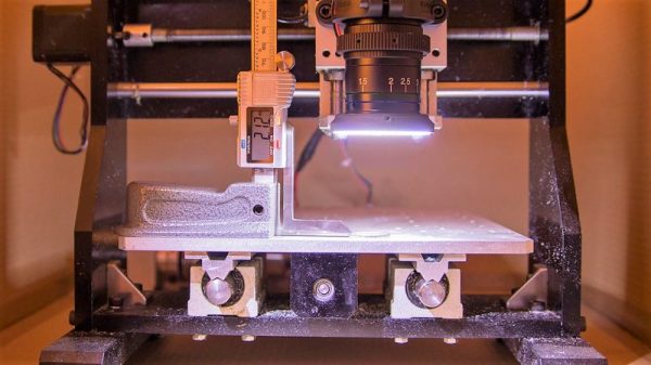
Although it appears [Saulius Lukse] purpose-built this rig, which consists of a microscopic lens on a digital camera mounted to the Z-axis of a small CNC machine, we suspect that anything capable of accurately and smoothly transitioning a camera vertically could be used. The idea is simple: the height of the camera over the object to be measured is increased in fine increments, with an image acquired in OpenCV at each stop. A Laplace transformation is performed to assess the sharpness of each image, which when plotted against the frame number shows peaks where the image is most in focus. If you know the distance the lens traveled between peaks, you can estimate the height of the object. [Salius] measured a coin using this technique and it was spot on compared to a caliper. We could see this method being useful for getting an accurate vertical profile of a more complex object.

From home-brew lidar to detecting lightning in video, [Saulius] has an interesting skill set at the intersection of optics and electronics. We’re looking forward to what he comes up with next.

Beyond Control: Maths Of A Control System

Control systems are all around us, and understanding them is going to make you much better at hardware design. In the last article — Beyond Control: The Basics of Control Systems — we looked at an overview of what a control systems are in general with the example: “everything in between water and time is a control system”. We also observed control systems in nature, where I described my keen ability to fill a glass of water without catastrophic results. That discussion involved the basic concept of a block diagram (without maths) and we expanded that a bit to see what our satellite dish example would look like (still without maths).

I promised some big ugly maths in this article, and we’ll get to that in a bit, never you fear. First let’s have a look at how some basic elements: resistors, inductors, and capacitors are defined in the time domain. Don’t let these first few definitions turn you off. No matter how you feel about calculus, you don’t necessarily need to fully understand each equation. What’s more important is how the equations themselves combine to solve the circuit. Also important is that I will do everything possible to get out of doing difficult math. So stick with me through the article and you’ll learn that agony-saving trick for yourself!

A quick recap on transfer functions before we get going might be beneficial. A control system is used to define electromechanical behavior. For example: our satellite dish (from the previous article) at some point will need to be moved from one position to another position and as control engineers it is our job to determine just how this action will take place. I’m not talking about setting the mood for the big emotional robotic rotation, more like: not damaging the equipment or any people that might be nearby when moving the dish. For many reasons the dish would need to be moved with extreme care and in a very precise manner. The control system is the mathematical definition of that movement. Often the maths of the definition are nasty differential equations, (remember I’m avoiding any math that can be avoided, right?) so, instead of using differential equations to define the system, the transfer function will define the system with algebra, relating the output of the system to the input.

Continue reading “Beyond Control: Maths Of A Control System”