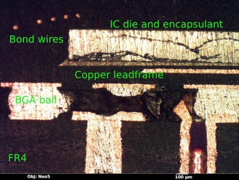
[Andrew Zonenberg] has crossed a line in his electronic hobby projects. The Ball Grid Array (BGA) is a type of chip footprint which most hobbyists leave to the professionals. But he’s learned the skills necessary to use them in his projects. Recently he ran a test batch to show off his soldering process and illustrate one of the errors a novice might make.
For those that are unfamiliar, the BGA footprint is notoriously difficult to accurately solder because it consists of a large grid of tiny points covering the bottom of the chip. There’s no way to get in there with an iron, so soldering depends on accurate placement of solder paste and chip, as well as a near-perfect reflow cycle. Often times it’s difficult for the professionals too. Many blame the heat-failure of Xbox 360 on the complications of the BGA connects for one of the console’s chips.
For this experiment [Andrew] wanted to show what happens if you include vias in the BGA footprint. It’s fine to do so, as long as they’re capped. But if a standard via is included, capillary action ends up pulling the solder down into the via instead of making a connection with the chip. The image above is a cross-section of one such uncapped via, seen on the far right.
[Thanks George]


