This hack shows how to make a dumb terminal out of a keyboard, LCD screen, and an 8-bit microcontroller. From time to time, a portable dumb terminal can be handy for when you have to rescue a headless server that’s acting up or if you are building a minicomputer out of a WRT, or if you just want to learn how to run a keyboard and LCD screen with a microcontroller. This super simple serial terminal will use RS-232 to control a headless linux system. Additionally, you might want to check into some of the command line interface programs that allow web browsing, AIM and IRC chatting and more directly from the terminal, but nothing beats being able to track your pizzas with this device.
The Linux system in question here will be Linux Mint. It’s a young distro based on Ubuntu that’s gaining a lot of attention lately, though the principles can be used for other Linux distros.
The Hardware:
For this How-To we’ll be using an ATMEGA128 running at 16MHz. Since this device will be communicating through RS-232, we’re going to need a level shifter. RS-232 uses 12 volt signals which will fry our 5V microcontroller. To fix this problem, we’re going to use a MAX233 chip.
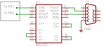
This is the schematic of the level shifter circuit.
I’m using the ET-AVR stamp module with the stamp board for this project. This dev board is cheap and has the essentials built in. I’ll be using the on board power supply and the MAX232 RS-232 level converter.
The LCD chosen for this project is a very common 4×20 character LCD. These LCDs are really easy to control with a microcontroller(PDF), and even without one(PDF). The HD44780 chip allows for several bit widths for parallel programming, as well as commands, and even custom characters. This LCD has nice software library, which makes it even easier to use.
A more attractive choice would have been to go with a graphical LCD, which are also supported by our library, however, we only had the character LCD on hand.
A common AT keyboard will be used for character input, again these aren’t hard to find, you probably have an extra one laying around somewhere .
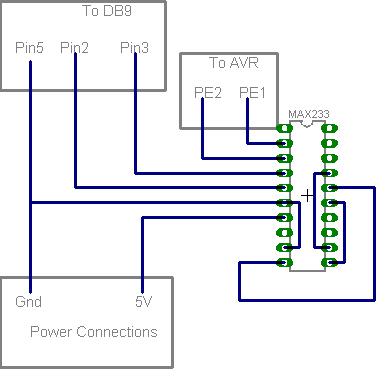
If you don’t want to buy the ET-AVR, you can build the circuit for this hack yourself. (Click for larger pic).

A full parts list of above circuit: :
| Part | Jameco Part # | Futurlec Part # |
|---|---|---|
| Atmega128 IC | 1406045 | ATMEGA128-16AC |
| 16MHz Crystal | 14453 | CRY16.000 |
| DB9 Connector (female) | 15771 | DSUBSCF9 |
| DB9 Hood | 1719922 | DSUBCH9 |
| MAX233 Level Converter | 106163 | MAX233CPP |
| 22pF Capacitor (x’s2) | 332340 | C022PC |
| 0.1uF Ceramic Capacitor | 151118 | C100UC |
| 220 ohm Resistor | 690700 | R220R14W |
| 10k ohm Resistor | 691104 | R010K14W |
| 10k Potentiometer | 255522 | TRIM10K |
| 6 Pin Minidin (optional) | 310789 (cut) | MINIDIN6PC |
| 4×20 Character LCD | 658873 | BLUELCD20X4BL |
| AT Keyboard | 319812 |
If you would like to use the ET-AVR or some other dev board, you can use this parts list:
| Part | Jameco Part # | Futurlec Part # |
|---|---|---|
| ET-AVR stamp module | ET-AVR STAMP | |
| ET-AVR stamp board | ET-AVR STAMP | |
| ET-AVR programmer | ET-AVR ISP | |
| DB9 Connector (female) | 15771 | DSUBSCF9 |
| DB9 Hood | 1719922 | DSUBCH9 |
| 220 ohm Resistor | 690700 | R220R14W |
| 10k ohm Resistor | 691104 | R010K14W |
| 10k Potentiometer | 255522 | TRIM10K |
| 6-Pin Minidin (optional) | 310789 (cut) | MINIDIN6PC |
| 4×20 Character LCD | 658873 | BLUELCD20X4BL |
| AT Keyboard | 319812 |
The Software:
We used WinAVR with AVRlib installed. AVRlib is a set of libraries that can run servos, set up A/D conversions, etc. It can do pretty much anything else you need it to do. To install WinAVR, get the newest version here and follow the directions on the installer. We generally don’t follow the directions here for installing AVRlib and place it into the include folder of WinAVR installation found at C:/WinAVR/avr/include/AVRlib. This way your included headers are easier to see and find.
eg. #include <AVRlib/servo.h>
Once this is done, you can open up Programmer’s Notepad and begin coding. We’ve already written the code for this project (with room left over for some adventurous readers to modify).
The Keyboard Protocol:
Keyboards use a simple serial communication setup. There are only 2 lines, the DATA and the CLOCK. Generally, nothing is happening on these lines (both the CLOCK and DATA lines are high) until you hit a key. Once a key is pressed, the DATA line goes low. Shortly thereafter, the CLOCK falls. The clock will go for a total of 11 cycles. As this happens, data must be read form the DATA line on the falling edge of the clock. The data is sent from the keyboard in reverse (least significant bit first) with a parity and a stop bit.
The overall data package is:
| Start Bit | D0 | D1 | D2 | D3 | D4 | D5 | D6 | D7 | Parity | Stop Bit |
The Start bit, Parity bit, and Stop bits are going to be ignored in this simple hack.
After the keyboard sends a key’s scancode, it also sends a 0xF0 when the key has been released.
Looking at an example, it is easier to understand. Imagine the ‘m’ key has been hit on the keyboard. The data line goes low to make a start bit, then the scancode is sent with the LSB first, then the parity (odd parity) and a stop bit. Since the scancode for ‘m’ is 0x3A, we should get that value in the data portion of the package. Again, the keyboard sends data LSB first, so since we are expecting 0x3A (binary 00111010) we will actually get the reverse of that (binary 010111100). Just remember to read the data bits from right to left to make it easier to see the scancode. After the data, we’ll receive a 1 in the parity bit to make the package odd parity, then the stop bit. After the scan code has been sent, the keyboard will send another scancode when the button has been released. This release code is always 0xF0 and can be ignored, and it gets handled in the code.
So when ‘m’ is hit, the keyboard sends :
| 0 | 0 | 1 | 0 | 1 | 1 | 1 | 0 | 0 | 1 | 1 | = ‘m’ or 0x3A |
| Start Bit | D0 | D1 | D2 | D3 | D4 | D5 | D6 | D7 | Parity | Stop bit |
| 0 | 0 | 0 | 0 | 0 | 1 | 1 | 1 | 1 | 1 | 1 | = Release (0xF0) |
| Start Bit | D0 | D1 | D2 | D3 | D4 | D5 | D6 | D7 | Parity | Stop bit |
A more advanced explanation on how this works can be found elsewhere.
We must only read the data line as the clock falls to make sure we get good data. We attempted to do this using an external interrupt on the ATMEGA128 and AVRlib’s external interrupts routines. This proved more complicated than it needed to be. We then remembered that not too long ago Sparkfun had posted about some kind of keyboard widget on their site that used an AVR. The code for their keyboard reading routine was really simple and didn’t use external interrupts at all. We modified the “getkey” routine from the one [Nathan] at Sparkfun wrote for their key-counter widget.
Once the scancodes have been read, they must be converted into something useful. As far as we could tell, keyboard scancodes have no mathematical relation to ASCII code so we set up two ASCII lists. Each list is actually an array of ASCII characters. One list has all the values for shifted characters, and another list has the values for unshifted characters. We looked up the ASCII value for each scancode and placed them in the array in order. This allows for a simple way to return the ASCII value of a given scancode.
When you hit the ‘h’ key for instance, the program catches the scancode 0x33 and goes to the 0x33 rd value in that array, which happens to be 0x68, the ASCII value of ‘h’. The resulting ASCII character is sent to the LCD and to the UART, both being controlled by AVRlib to make them easier to deal with.
There are a lot of 0s used as placeholders in the arrays. This is because AVRlib automatically loads the LCD’s CG RAM address 0x00 (the ASCII code for NULL) with a character. Basically, if those codes are send to the LCD, it will just look like garbled mess. We used ‘0’ so we could tell what was going in if that were the case.
Extended keys are not currently supported. The Function keys (F1-F12) have been given normal functions used in Linux, but not supported by the rest of the program. For example, pressing F1 sends the same command as “Ctrl+X” in Linux. See the code for the other function keys. Not all the keys are used (purposely) so if you want to add custom functions to the terminal, there’s plenty of space to.
The UART:
The ATMEGA128 has two UART ports. Using the first one (UART0) characters can be sent from the AVR to the terminal, and vice versa. The UART is initialized and set to 9600 baud, 8-bits, no parity, one stop bit. Make sure to set the terminal program to the same settings. We’ll modify Linux later to make sure the settings match.
With AVRlib, using the UART is a breeze. Simply initialize it, give it a baud rate, and you can start sending and receiving data.
Fiddling with Linux:
You’ll either need a monitor and keyboard on the Linux machine, or SSH into the machine and set this up.
There are several good guides on the internet for setting up a Linux machine to use a serial console. However, Linux Mint is based off of Ubuntu, which is a bit different than most OSs when it comes to setting up serial access at boot. This guide explains the basics, but we’ll need to tweak that a little to make it work for us.
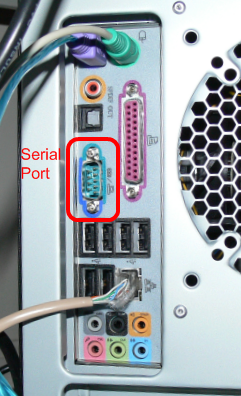
First you need to find out if you even have a serial port on your machine. Look at the back and try to find a DB9 connector.
Now you will need to figure out what that serial port is referenced on your machine. Open a terminal window on the machine and enter the following command:
======================================
$ dmesg | grep tty
======================================
The output will be something like this:
======================================
[ 35.742036] serial8250: ttyS0 at I/O 0x3f8 (irq = 4) is a 16550A

[ 35.742435] 00:08: ttyS0 at I/O 0x3f8 (irq = 4) is a 16550A
======================================
This shows that we have 1 serial port on this particular machine. And it is called “ttyS0”.
Now we must set up a way of logging into the serial console. This is handled by the getty process. This process will open the tty port you specify and send a login prompt.
To set this up, we need to create a file in /etc/event.d called ttyS0. Open up your favorite text editor and type in the following:
======================================
start on runlevel 2

start on runlevel 3

start on runlevel 4

start on runlevel 5
stop on runlevel 0
stop on runlevel 1
stop on runlevel 6
respawn
exec /sbin/getty -L 115200 ttyS0 vt102
======================================
Now save this file as /etc/event.d/ttyS0.
Now, that’s fine for the regular users on the machine, but to do things as root, there will have to be a pass in the /etc/securetty file. Go to /etc and use a text editor to open the securetty file. (That’s “securetty”, not “security” ).In this file, type “ttyS0”. This allows that port to have root access. Save the file and close the editor.
Now the final step is to have the console available when the machine boots. To do this, we must modify the grub bootloader. You have to go to /boot/grub and edit the menu.lst file. First go there and make a clean copy of the menu.lst file:
======================================
cp /boot/grub/menu.lst /boot/grub/menu_orig.lst
======================================
Now open menu.lst in a text editor and type the following
======================================
serial --unit=0 --speed=9600 --word=8 --parity=no --stop=1

terminal --timeout=10 serial console
======================================
This first line tells grub that you want ttyS0 to be used (–unit=0) with a baud rate of 9600 (–speed=9600) using 8n1 (–word =8–parity=no –stop=1)
The second line says to display the terminal on both the serial console as well as the screen, if there is one.
If you want to watch the boot messages on the serial console, you can add the following line to the end of the “kernel” line in this file:
======================================
console=ttyS0,9600n8 console=tty0
======================================
Save this file.
Now you should have access to the serial console when you boot, but the default shell is bash. This is bad because bash sends a lot of extra characters when it executes commands. On many terminals, these characters are stripped from displaying, however, it is hard to do that on an LCD, and with only 80 characters, we don’t have much room to spare on our screen. We need to use something a little simpler.
[Fabienne] suggested using sh as the shell to get rid of bash’s weird characters. This worked during tests, so we made it the default shell on the machine. This allows it to automatically load during the boot, making it much easier to use with the device we’ve just made.To do this, simply open a terminal window and type:
======================================
chsh
======================================
This will ask you for your password. Once you enter it, you will see a screen like this:
======================================
Changing the login shell for <username>

Enter the new value, or press ENTER for the default.

Login shell [/bin/bash]
======================================
At this point you need to type the following:
======================================
/bin/sh======================================
Hitting ENTER again will save this new setting.
Now you are ready to connect the device and see it in action!
Connecting the device:
You can play with this on a windows machine, but its real power is with a Linux machine. If you have a Windows machine, you can now communicate to the device through hyperterminal or some other terminal program. Just plug in a serial cable to the DB9 plug and set the terminal to 8n1 as mentioned above. Typing on the keyboard will display on the terminal and on the LCD.
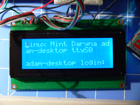
To use it with the Linux machine, plug in the DB9 to the serial port on the computer, and turn the machine on. The first that that should happen is that the system will ask you to “Press any key to continue”. Hit anything on the keyboard to begin loading the OS. After pressing the key, you should see all the boot information scrolling on the screen. Once this stops, hit “enter”. This will bring up the logon screen (remember setting up the getty?).
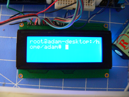
Type your login name, and hit enter, then your password. As with most Linux systems, typing in the password field will NOT print to the screen. Go ahead and get an “ls” of your home directory. Notice that the screen isn’t large enough to show all the files and folders. We’ve written in a simple single screen buffer that will show the previous 4 lines displayed on the screen. So this kind of emulates a “Page Up” function.
Now you have the code, and the hardware lists, lets see what you can do with it.


Nice, this is sooo detailed, I actually might try it.
Cool stuff, just one thing:
On the full schematic, at the top-left, theres a 10k resister (R3) that goes nowhere. Shouldn’t that be attached to something?
It is, VCC which should be 5 VDC.
Just fixed the missing VCC for the reset circuitry in the main schematic. Thanks for catching that.
very cool, wish i knew abit more about micro controls then i’d give it a shot.
Great How-To!
useful, simple, detailed, and informative!
Keep up the great work Hack-A-Day!
great tutorial adam
Avrs suck. More PICs please.
Kudos on the well written article, i loved the detail.
This would be the perfect job for a propeller. Hooking up and controlling an LCD ,PS2 keyboard and serial port is so easy with that mcu it almost feels sinful. Not only would it be cheaper if you used the prop protoboard, you’d have plenty of leftover cogs and in/out pins left on the prop to use for other things.
this is great
I’m impressed.
Great project! I’ve always wanted to build this exact project for working on headless boxes. If you add some minor terminal functions to enter hex values it would also be a great dev tool for probing a serial bus (SPI and I2C as well). You could also snoop unknown protocols.
Awesome! Just what I needed for this years music setup for Roskilde festival. An Asus WL500gP router, USB sound card, bluetooth with MPD and pympcd for controlling it from my cellphone. Oh yeah, and a 100 GB harddrive.
…and if I can find the time, a display as well.
Thanks for sharing this!
You should make this easily with arduino there are drivers for both LCD and Serial line (or Serial over USB)…
Now this is my kind of hack. Reading through it I noticed the big dead space at the top of my chunky “media” keyboard- about as big as, say, a 20*4 LCD? I think one of these interfaced to a gumstix or similar tiny computer would be incredibly useful for robotics- you want to tweak your robot? plug in a keyboard and fire it up.
Great article, keep up the good work. But isn’t atmega128 somewhat an overkill?? you could easily do the same thing with atmega8/16/32 (think arduino). Price is not a problem here, but you can get those in DIP and so you can etch your own board and make it even smaller. + it might not be a bad idea to emulate usb CDC protocol on it as well, so you could connect it also via usb, for perhaps HTPC status lcd. Atmega32 running at 16mhz has more than enough horsepower to run such configuration.
wonder if you can do it with say a TI calc……..already has a graphical lcd and serial port
Looks like a lot of fun – I might actually try this someday.
This is very cool, is possible to run a slightly bigger screener? Say wider and taller? If so this could be a very hand tool for network/teleco engineers.
it should be possible to use any character lcd that uses HD44780, i think that 4×40 are the largest. You could of course always use a graphical lcd, but you’ll have to write some extra code for that…
very cool and detailed, thanks
^ Jesse krembs, this is exactly what my idea is too. the 128×64 screen would be great, and should not be too hard to get it to work… right? I’m thinking about trying to make a single unit, keyboard and screen with a serial port waiting for you to plug something in to it, i.e. a serial cable for a headless machine, or a one of those super sweet blue Cisco cables, etc….
Thus far the total cost would be less than $50, so it is a reasonable project to attempt….
thats a really good idea, would be good to make it fit in a 3.5 or 5.5 inch bay depending on what size screen you want. would be perfect for a duke box pc or something similar
I was off on the $50…. miss the Stamp board, I believe the link is wrong in the list. Also the 128×64 graphical screen does not use the hd44780 or equivalent controller it uses the ks0108b controller.
GREAT! i study mechatronics in germany und i wish our prof would be able to explain stuff that detailed!
good job, i love it!
I always just haul around my ADM3-A (with lowercase extension!) or the VT-220…
Can i buy one? :)
I want one sooo bad! :)
Will you post the eagle cad schematic file? I was planning the exact same project, and I want to start etching a PCB right away. I’m planning on a single sided board with surface mount components, mounted in an altoids tin.
Ethernet support would make this project even more versatile. And power over ethernet would eliminate the need for extra wires. Oh, the possibilities…
this is EXACTLY what I’ve spent the last week looking for! Thanks.. Acouple questions though..
Do I have to wire the keyboard up through this for me to able to use the keyboard?
Where can I find the LCD screen that is in the picture? The on with blue backlight, because on that one site it says it doesn’t have a blacklight..
Thanks
very nice article! more stuff like this please :)
@rune: oh hey, i’m going to roskilde festival too! how nice
For anyone that cares, a graphical lcd (128×64) would work excellently with this project. AVRlib even has the header file for ks0108! I am definitely trying this!
Can i use a any bigger display ?
chris: the biggest display you can get is probably a 40×4.
It would be more expensive.
Heyho guys. Mayb you can help me: i’ve ordered a lcd from an online shop: http://www.pollin.de/shop/detail.php?pg=NQ==&a=NTc2OTc4OTk=
but now i cant find any information how to connect the display to the pc. the datasheets are only for the chips on the circuit but not how the circuit works but cant find anything about the connection. lcd hype didnt work with the chip.
has someone any suggestions to get the lcd working, pls mail me: blood_surfer@gmx.de
Thx B_S
hi,
could you send me the code or refresh the link to it as it is currently not working
thanks
Hi;
I really need to build this.
However the link to the code .zip file is a 404.
Would you post a link for it please.
Same! Have you developed anything yet?
I’d love to try doing this! I was thinking of using a VGA port, though. That way, I can either hack an old CRT to create the old-school CRT DT, or integrate it with an LCD.