For years, Microchip PIC microcontrollers dominated; PIC16F84 hacks and projects are everywhere. The 8-bit 16F and 18F lines are supported by several coding environments and easy-to-build serial port programmers. Microchip’s 16-bit PIC24F is cheaper, faster, and easier to work with, but largely absent from hacks and projects.
We recently used a Microchip PIC24F microcontroller in a mini web server project, but didn’t find many introductory references to link to. In this article we’ll cover some PIC 24F basics: support circuitry and programming options. We’ll also talk about our favorite features, and how we figured them out. Our next article will outline a web server on a business card based on the PIC 24F.
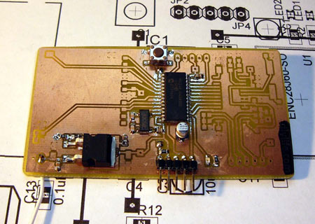
The basic circuit
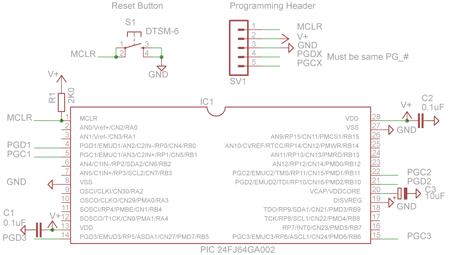
This is the basic support circuit (full size .png) for a PIC 24FJ64GA002. Some helpful documents are the code examples, application notes, individual datasheets, and 24F family manual.
Main system power supply
Peripherals and pins on the 24F PICs operate between 2.0 and 3.8volts. This is a big advantage over older PICs because the 24F can directly interface modern 3.3volt components like SD memory cards. Some 16F and 18F PICs will run at 3.3volts, but usually at drastically reduced speeds. As always, put a 0.1uF capacitor between each power pin and ground to decouple the chip from the power supply (C1, C2).
Core power supply
The processor core requires a separate 2.5volt supply. A built-in 2.5volt regulator can be enabled by connecting the DISVREG pin to ground, and placing a 10uF capacitor between the Vcap/VDDCORE pin and ground (C3). We’ve not experienced any problems using a 10uF low ESR electrolytic capacitor, but in the future we’ll use a tantalum capacitor as specified in the datasheet.
Speed and crystal
PIC 24Fs have a max clock speed of 32MHz, and complete one operation every 2 clock cycles for a top speed of 16 million instructions per second (MIPS). Most 24Fs have an internal 8MHz oscillator, but you can also use an external crystal for a more precise timebase. An internal phase lock loop (PLL) can multiply any clock signal by four.
We used a common option: 8MHz internal oscillator multiplied by four (32MHz), with full IO functions on the external oscillator pins. The clock mode is set with CONFIG2. Use these settings to run a PIC 24F at 32MHz using the internal oscillator and PLL:
// Internal FRC OSC with 4x PLL @ 32MHz
//from p24FJ64GA002.h:
//FNOSC_FRCPLL - internal oscillator
//OSCIOFNC_ON  - enable the oscillator pins as IO
//POSCMOD_NONE - Primary (external) oscillator disabled

_CONFIG2(FNOSC_FRCPLL & OSCIOFNC_ON &POSCMOD_NONE)
Programming connections
Microchip’s standard 5 wire in circuit serial programming (ICSP) connection is used to program the 24F. ICSP consists of a clock line (PGC), bi-directional data line (PGD), master clear and reset (MCLR), and connections to power (V+) and ground (GND).
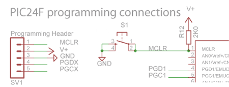
The MCLR function resets the chip when voltage levels are too low to operate. Enable it with a 2000 (2K) ohm resistor (R12) from the system power supply to the MCLR pin. Optionally, add a button (S1) from MCLR to ground for a manual reset switch. The programmer also connects to the MCLR pin to reset the PIC and control programming modes.
PIC 24Fs have several sets of programming pins labeled PGDx and PGCx. Choose the set most convenient for your design. One catch: you can’t use the clock pin of one set and the data pin of another, you have to use the same pair.
The primary pin pair used for debugging is programmed in CONFIG1 with the ICS_PGX option. This only effects debugging; programming is still possible from any pin pair.
_CONFIG1( ICS_PGx3)
Coding and Programming
Unfortunately, the 24F can’t be programmed with the hobbyist-favorite serial port programmers. These are usually 5volt programmers that place 13volts on the MCLR pin. 24F PICs are rated for 3.8volts maximum on the MCLR and programming pins, old serial port programmers will destroy them.
The ICD2 is Microchip’s cheapest programmer for the full 24F line. An education discount is available if you have a .edu email. There are numerous clones too, most notable is the Olimex PIC-ICD2 clone, also sold by Sparkfun. We’ve never used it, but it’s supposed to be an exact clone. You can also try your hand at building a DIY ICD2 clone, we’ve had luck with the PiCS Rev B in the past. You’ll probably need to build an adapter to use a homebrew ICD2 with a PIC 24F.
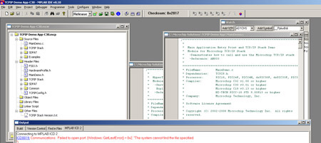
MPLAB is a free development environment for coding, compiling, and debugging all PIC microcontrollers. We like to program in C, so we downloaded the free, evaluation/student edition of the Microchip C30 compiler that integrates into MPLAB. HI-TECH’s C compiler is a fairly popular alternative if you’re not thrilled about MPLAB.
Microchip’s low-voltage 18FxxJ line, such as the Ethernet enabled 18F97J60, can only be programmed a few hundred times. That’s fine for production, but really unfriendly to a developer. We’re exceedingly happy to note that the 24F can be programmed at least 10,000 times.
New features and improvements
We made a list of the things we liked best about the PIC 24F after using it in a project. Not all of them are new, sometimes little improvements make designs much simpler.
8-bit vs 16-bit
C programmers won’t notice many differences between 8-bit and 16-bit architectures. Native 16-bit math operations will save you a few cycles if you do 16-bit integer math. Memory and registers are 16-bits long, meaning the default 16-bit variable type counts to 65,536, rather than 255.
Peripheral pin select
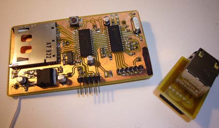
Peripheral pin select (PPS) is our favorite feature on the PIC 24F. The digital peripherals SPI, UARTs, timers, etc can be connected to almost any pin on the chip.
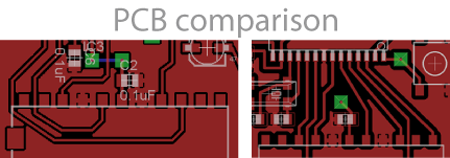
PCB designs get really creative because the pin arrangement on a microcontroller rarely matches that on the peripheral you’re interfacing. Compare these two designs. The design on the left uses looping, winding traces to connect a SD card without jumper wires. On the right, we used PPS to assign pins in a way that lined up perfectly with the SD card. We spent caffeine fueled nights routing the board on the left, but only hours on the other. We’ll find it difficult to ever work with a PIC 16F or 18F again because of the complete and total awesomeness of PPS.
Input and output pins are assigned differently: pins are assigned to inputs, outputs are assigned to pins. A peripheral input, such as the “serial data input” (SDI) signal of an SPI interface, is set by putting a pin number in its register. In the C30 compiler, SDI of SPI1 and SPI2 are assigned like this:
// Inputs
//SDI1 B12/23/RP12
//SDI2 B1/5/RP1

RPINR20bits.SDI1R = 12;            //SDI1 = PORTB12

RPINR22bits.SDI2R = 1;            //SDI2 = PORTB1
Output functions are handled in the opposite way. A group of registers represent the programmable pins (RPORx). Peripheral outputs are assigned to each pin. Assign the SPI “serial data output” and “clock output” lines like this:
// Outputs
//SDO1 B11/22/RP11   //CLK1 B10/21/RD10

RPOR5bits.RP10R = SCK1OUT_IO;     //RP10 = SCK1

RPOR5bits.RP11R = SDO1_IO;        //RP11 = SDO1

//SDO2 B3/7/RP3       //CLK2 B2/6/RP2

RPOR1bits.RP2R = SCK2OUT_IO;     //RP2 = SCK2

RPOR1bits.RP3R = SDO2_IO;        //RP3 = SDO2
Check the device datasheet and the IO with PPS datasheet (PDF) for a complete list of peripheral (RPINRxx) and pin (RPORx) registers.
Individually configurable pull-up/pull-down resistors
Pull-up and pull-down resistors hold inputs at a known level when there’s no other signal. Illustrated below on the left (S1), a pull-up resistor (R1) normally holds the signal high (1). A button press pulls the signal to ground (0). Without a pull-up resistor, the value on the microcontroller pin will fluctuate wildly (state undefined) until a button press pulls it to ground (0).
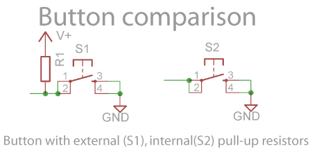
Internal pull-up resistors make it easier to route a button on a circuit board. An internal resistor holds the signal high until the button pulls it low, saving a resistor and power supply trace (S2). PIC 16Fs and 18Fs sometimes have an all-or-nothing pull-up on 8 pins, but the 24F adds individually configurable pull-up resistors. See the IO datasheet (PDF).
CRC hardware module
Cyclic redundancy check (CRC) values are used to verify the integrity of data. Your PC calculated CRCs for the TCP packets that carried this page over the web. The 24F has a hardware CRC module that does tedious CRC calculation without processor involvement. Check out the datasheet (PDF) and example code (ZIP).
Real time clock and calender
Microchip added a hardware real time clock and calendar module (RTCC) to every 24F. It’s always been easy to add an interrupt-based clock to a microcontroller, but this module takes care of everything without timing concerns.
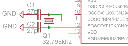
The RTCC module requires a 32.768khz watch crystal (Q1) to be connected to the SOSCx pin pair. Don’t forget 2 suitable capacitors for your crystal, we used 27pF (C1,C2). There’s a datasheet for the RTCC module (PDF), and example code (ZIP).
Package sizes
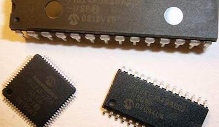
Microchip continues their tradition of offering products in a range of package sizes. Low pin count parts are available in through-hole (DIP) and several surface mount sizes. As with all manufacturers, though, the largest, coolest, chips are only produced in surface mount packages. Microchip is a fan of 64, 80, and 100 pin thin quad flat packs (TQFP), a square chip with an equal number of pins on all sides. TQFP isn’t terribly difficult to solder, but the circuit boards can be a pain to make at home.
Conclusion
The past was dominated by 8-bit PIC 16F and 18F-based microcontroller projects. 16-bit PICs, however, have been largely neglected. If you’re already considering a PIC for your next project, check out the 24F series. The peripheral pin select feature alone is worth the switch — it simplifies circuit boards, reduces routing time, and saves board space. We were able to fit an entire PIC 24F web server on a business card using a home-etched PCB. Our next article will introduce this simple server prototype.
The project archive (ZIP) contains the base schematic for the PIC24FJ64GA002, and a custom 28pin part we added to an existing PIC 24F part library. Both are for use with Cadsoft Eagle, a freeware version is available for most popular platforms.


Whoops, comments were off for some reason.
wow, *excellent* article! full of great info. I will definitely check out the pic24f now
i like the addition of the built-in pull-up/-down resistors and the real time clock — very neat! the peripheral pin select seems very useful as well. and to think that i almost swore off pic’s after seeing how sane 8051 cores are compared to the pic18f’s — i think you’ve convinced me to stay with microchip
mplab feels like software from the windows 3.1 days — the built in editor is horrendous. make sure you check out piklab under linux — its a great ide for pic’s, and easily interfaces with all toolchains (sdcc, or even windows ones like C18 via wine). it has programmer support for icd2, and debugging support is in progress.
sdcc is a great assembler/compiler/linker toolchain for many microchips, and it has great support for most pic’s. additionally, its a lot better than the C18 compiler, which has some very weird conventions. microchip is known for their non-standardness, and at least sdcc seems to bring a little sanity back to programming pic’s
finally, i bought a usb icd2 clone off ebay from a seller named mdfly (or something similar). its served me very well, and programs & debugs just fine. on top of that, it was *very* inexpensive!
cheers, and thanks for the great info on the pic24f
Wow, I never realised that it was possible to get a pic that has programmable hardware components, I might just have to look into switching over from my old standby pic18f2550. The rtc could come in handy as well; although it seems odd that you can’t set its clock off the main pll using a big old divider.
Can’t wait to see the webserver writeup; I have been waiting for someone ot release a decent webserver app for a pic ever since I saw an avr based one years ago!
project archive -> DOWN
it looks like there is a problem with linking the project archive, here’s a temporary link.
One more try:
http://www.whereisian.com/files/PIC24FIntro.zip
James, welcome!
you’ve taken your first steps into a larger world.
I’ve bookmarked this site for many many (many?) years.
it is beloved, at least by me.
Hope you come to feel the same. :D
Very Nice! I have been wanting to get into the world of pic for a while now, but was looking for the right inspiration to get started. Looks like this will be the one.
I used the Pic24f for Puzzlemation. Microchip has free libraries for TCP/IP and reading a FAT filesystem off an SD Card – not bad for a $3 chip.
General Downsides of the Pic:
Read the Errata first! It had some horrible issues with I2C and the AtoD in the earlier versions of silicon. (collision issues and a slower sampling speed)
Don’t use the internal Pull-ups to interact with an external device that uses an open-collector output. The internal pullups don’t pull the device up to Vcc, but the port set to look at it compensates by having a different threshold.
Realize that analog functionality cannot be re-routed.
When you are using a analog pin as a digital output, remember to disable the analog functionality first.
Power: Pay attention to the maximum current per pin (especially important on the PIC24H and the DSPIC33).
And last but not least: The internal clock runs at Osc/2. This means 2 clock cycles for every instruction.
Good luck (and enjoy your vectored interrupts :)
This is a great article- it really shows how to get the most out of a PIC24. If you like the PIC24, check out the PIC32- a 32 bit 80MIPS processor with lots more memory, and is pin compatible with the higher pin count PIC24s (though not the one in this article). You can program all microchip parts (8-32 bit) with the PICKIT2 ($35), which is lots cheaper than the ICD2, though you have to use a separate program.
This is great! I designed a board (centered around the F84) that did this in sophomore year of high school! Worked like a charm… and I made 20 of em. They were around the size of this one, but weren’t SMT. I had this awesome company called PCB123 (pcb123.com) produce them for me, which was cool because of the quick turnaround.
this is awesome
designin it is not a leet
I’d be interested in BUYING one of these from anyone that can successfully build one for me. Email me, or drop a message on my website shoutbox.
What purpose could a web server of this low capactiy serve as a use? I have alot of webserver projects, some requiring high end rackmounts and some that could run on systems as old as atari keybaords (if they could connect to the net of course lol)
So what could this little project handle? Anyone have any feedback?
Cool stuff!
I developed something similar, few months ago.
FTPmicro embedded web server and ftp client, schematics and firmware are Open Source to download
(stack microchip with some modification – feed rss reader – fat16 – ftp client)
Example application: ANSA news on the LCD or sending emails with picmicro
http://dev.emcelettronica.com/ftpmicro
Anyone have a link to a website that this thing is serving? I can’t seem to find one.
Please if you know where to by all the parts and the board , i will apreciate.
Tks
Carlos
I’m trying to find a cheap programmer for this board. I’ve already built it, but I didn’t worry too much about programming it at first.
This site looks somewhat relevant, but I don’t think it’s what I really want (may be helpful to others): http://www.melabs.com/support/3v_icsp.htm
Upon further investigation, it seems to me like the way to go is buy a $35 PICKit2 USB programmer from here: http://www.microchipdirect.com/productsearch.aspx?Keywords=PG164120
I found a site where someone made a similar programmer themself, though I don’t think it’s worth it in this case: http://www.mcuhobby.com/articles.php?article_id=7
According to the supported device list (http://www.microchip.com/stellent/idcplg?IdcService=SS_GET_PAGE&nodeId=1406&dDocName=en027813) the PICKit2 indeed can program the PIC24f used for this project. However I’m not certain it can program the PIC while it’s on the board.
If anyone could provide extra information on programming this thing, that’d be super awesome.
Cheers
VERY interesting info here! I was doing a project with the 16F876A – just got frustrated with software issues: 8 level stack, software can’t read it, no pushes, no pops. No local variables – just umpteen “temp” variables. And the contortions you have to go through to have some strings in ROM?
I looked at the 18F parts – 16 stack positions? Ugh. Went for the gold with the 24F and a REAL STACK. Would have gone straight to the 32bit parts except they’re apparently not available in DIP. And I’m not good enough at Toner Transfer ( yet ) to want to mess with surface mount.
Somebody wondered what such a small part could do – useful – as a webserver. I figure that any little gadget you might build that needs a console of some kind could do it with a server. Don’t need buttons, lights and switches. Don’t need fancy expensive displays, either. Just an Ethernet connector in front. Maybe a power switch. Or maybe not. Make the “front panel” as fancy as you want, it’s just HTML.
– Jerry Kaidor
Board built and ready to program PIC, need help with ICSP (which circuit to use..I found the various messages very confusing )
Any helpful pointers appreciated…..can’t afford the Microchip (commercial) programmers!
Thanks Dave
off topic a bit…
but where can a complete noobie go to start learning how to program PIC24f microcontrollers?
I have flashed some before..with other peoples HEX files.. but want to understand/leanr and start writing my own code to control/manipulate the chip.
thanks
Hey Dude, Yeah, it’s not a simple task learning to write the code but actually programming the PIC is relatively easy, the instructions that come with the programmer are straight forward enough.
There are lots of books around to teach programming but my old brain seems to prefer hardware :-)
I have my unit complete and working but our local ISP blocks port 80 so we had to change the code to run on 81, it works fine but still having local issues getting around the ISP / router and redirecting folks to port 81.
Dave
Ian very kindly gave us all a page with a link to where the live Micro Server V2 is running and discussion of firmware mods etc is taking place. This is an especially good place for folks new to the project to see how it all functions and get access to the latest topics, FAQ’s etc.
http://whereisian.com/forum/index.php?topic=51.0
That is so cool. This is why i love DIY things
Hi J.A. Glad you found the little server interesting….one of my pages was the control page for 4 LED’s (testing reliability of hardware with Ramon’s code update) and the other is up now with pictures of the inside of the one server.
take a looksee via this redirector link:
http://microserver.yolasite.com/
Dave
There seems to be a little something odd with your site when opened in opera . Its odd because everything is all twisted up looking. you may want to take a look at it. Also, in case you are interested I found a good site to get fast business cards online for cheap
its good to see the pic getting some love. Ive used pic’s since I taught my self to code in ASM. I always get the cold shoulder from hack sites because I use Pic. I just find the super low cost to implement smashes the code availability for things like arduino. Awesome post hackaday! Keep them coming !
Hey Jim,
Yes I agree the PIC’s are neat little devices and really quite capable….Ian did a great job with the little server too…..I have to say that I’ve gone over to the dark side recently though and have been playing with another PIC server(33FJ64) in the WIB design from Silicon Chip mag in Australia…great little server and seemingly bullet proof.
Unfortunately though Mauro doesn’t share his source code like Ian did.
Take a looksee here: http://siliconchip.com.au/cms/A_111778/article.html
Great to hear of more builders though !! Dave
Vancouver BC Canada.
that is very cool really
I’ve used ICL3232 (=MAX3232) in a serial level converter, which takes RS232 level on one side and takes voltage supply from the other side and outputs at that level (either 3.3V or 5V). Good for chips like this that can’t take 5.
The WIB in my SMT version has proven to be bulletproof and a great little device, I recently added an LCD display with clock function that is kept accurate via an NST server, Brek in Australia reworked Mauro’s code (the original had 7 segment LED displays) :-( to work with the LCD and it has vertically scolling digits…..very neat looking.
Dave
@…: Ever seen a clock divider that divides by 488.28125? I don’t think so..
Hi, I really liked your project but the link for the project archive are not working. Can you or somebody else send me the project archives, it would be really helpful to me thx adam