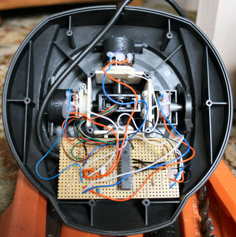
[Amr Bekhit] converted his gameport joystick to use as a USB joystick. Much like a universal USB joystick interface, this uses an additional microcontroller to talk to the serial bus while monitoring the controls on the stick. [Amr’s] discussion about creating HID descriptors is clear and easy to understand. What he’s laid out can be translated to any custom HID your heart desires. Give it a try with that old peripheral that’s been gathering dust in the corner.


Hot glue: adhesive of champions. :)
Nice job! It’s really good to learn about HID devices.
Anyone know if you could get force feedback up and running with a similar build? I have an old steering wheel with force feedback and a game port, would be really nice to be able to use that again.
@SheeEttin – Duck tape > hot glue, especially when you spell it that way :)
I couldn’t help but promote my own tool for creating and *editing* HID report descriptors:
http://digimend.sourceforge.net/#proj-hidrd
Though, it works only under *NIX currently.
Basically you could author your own descriptor in XML, convert another descriptor to XML and then edit it, or just dump a descriptor into a human-readable format.
Wow, this may be exactly what I have been looking for. I mooched an old gameport steering wheel and pedal set from freecycle, but the pots are clearly past their best because the values drift and jitter like crazy.
I’ve been meaning to replace them with optical encoders and Arduino-ify (sorry) but wasn’t sure how to make it appear to be a HID.
I just found this site – nice.
I second the force feedback comment.
I paid a lot for my sidewinder FF pro.
It would be nice to get it working under win7-64
So many things to do … so little time…
I have been working on my own usb joystick project based on this project.
http://starlino.com/usb_gamepad.html
It uses the mcc18 compiler. you should be able to program it as either a mouse or a joystick. I have a problem with it right now though. I think the 100k ohm potentiometers for x and y are too high resistance for th adc of the 18f2550. I was going to add a 1458 dual op-amp as a buffer. does anyone know if this is the right way to go?
I originally picked up a pickit2 to enable me to create my own HID’s for flight simulation. I have yet to actually make my own, but that is me being lazy. Great project!
@bait – If you can’t duck it… then ummm… forget it? :)
Awesome; keeping old hardware does pay off sometimes. ;)
I noticed he mentioned making a 6-button joystick with the two extra switches in the front. He uses a 4-button HID descriptor, and does not mention how to add buttons to the template, only that it can be done. The switches are wired to the PIC, but the resulting HID joystick has 4-buttons.
So has anyone made and USB to gameport adaptor yet?
As a project or as a product?
At least the product already exists. Anyway, AFAIK, the gameport is nothing but a connector whose each pin connects directly to one of the buttons, axis and so on the joystick. Look at this: http://en.wikipedia.org/wiki/Game_port
So, if I’m not wrong, we can consider this project as DIY gameport to USB adapter.
@3L_S4N70 Not exactly. In the standard gameport, the potentiometers are used as variable resistors. I believe that originally they used to discharge capacitors that were charged by “writing” to the gameport, and it was care of the software to count the time these took to get back to a logic 0. This meant that the joysticks would drift a lot with temperature variations, and were quite inaccurate at best. this still stands true for the gameport adapters, though I suspect they use a Wheatstone bridge, with the joystick’s potentiometers as an element, to compensate somewhat. From the wiring in the picture it looks like the joystick potentiometers are set up as voltage dividers, with the wiper picking up a voltage between the extremes at the opposite ends of the potentiometer. This means that the positioning is more accurate, and less dependent on the actual value of the potentiometer itself, as long as its resistance is high enough to limit the current between the supply rails.
@Brandano Yep, I guess you are right, he uses the potentiometers as voltage dividers (directly to the ADC). Well, it’s quite disppointing that to really have an accurate system, the joystick must be taken apart and modified. Anyway, for non-analog gamepads, this project can be used to make the gameport to USB adapter.
Hello all,
Thanks for the comments.
@Mike: When I first started the project, I did not know how to modify the joystick descriptor correctly, which is why I left it at the default 4-buttons. Now that I do know, I’ll change it to 6 buttons and update the website.
–Amr Bekhit