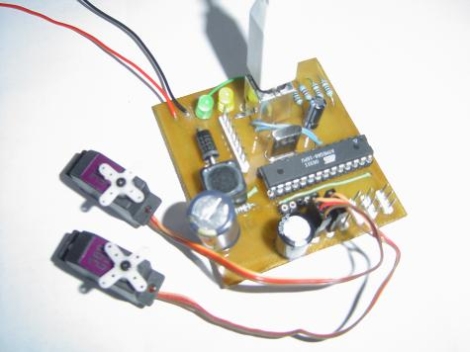
[dunk] constructed an easy to use AVR-based USB controller with the ability to drive up to six R/C hobby servos at once. While the USB-powered Atmega8 he used supplies the necessary PWM signaling for all of the servos, an external power supply rated up to 30v at 3A is necessary to provide the 5v of power each servo requires. His project is an extension of the USB servo controller built by [Ronald Schaten] and includes several significant upgrades. The addition of 5 more servos aside, [dunk] switched to AVRlib routines for multi-servo control and PWM management, as well as added the aforementioned power supply to prevent an excessive current draw on the USB port. His tutorial includes a complete parts list, Eagle PCB schematic, the required USB servo source code, as well as a sampling of commands that can be issued to the servo controller.


o.o he needs 90 watts to drive a couple servos? isn’t that a bit overkill? maybe if he is using industrial actuators… but for servos?
is he using PWM signaling or PPM signaling?
Nah. Check the article- he’s using a switching regulator for the input, so 7 volts would work fine- he specifies that the combined servo load needs to stay under 3A.
I presume it is PWM.
30v is definitely overkill, but 3A is not. Those small servos use about 5 watts (5v @1A from my tests) but only support voltages up to 6 or so.
He’s probably using a higher voltage supply to ensure that the current supply it up to spec.
I was prototyping a Guitar Hero playing robot and was surprised at just how much current those micro-servos actually draw. I had six servos and needed a touch under 3A when then were all making short but rapid movements.
I can’t let the confusion go on any more Hack-a-Day… When talking about power, voltage, and current you should use the proper terms. In this post, for example, you say “5v of power each servo requires.” Voltage is not a measure of power, it’s a measure of electromotive potential. I’ve seen this several times on the site and I don’t want the newbs to get confused by it.
Nice, I made a servo controller like that a couple years ago for an art installation by a glass artist & a musician. Based on the same ATmega8 and everything, with a serial port for configuring the software. The board in the picture is a spare that I built out with just the servo PWM pins in place, and I wrote a Qt app to toggle and/or poll pins so it worked sort of like a slow, cheap logic analyzer.
Good times!
ahh, he’s using both!
“I built it to control servos (and PWM motor controllers)”
If anyone wants to do this the real hard way,
I wrote up an 8-servo assembly language controller
for a Motorola 68HC11 in 1993. Look at servo8.asm
http://www.cs.uml.edu/~fredm/cher/contrib/
(Man, 1993? 18 YEARS AGO? Where did the time go?)
I’m very happy things aren’t as hard as they were in 1993.
This sounds like a perfect Picaxe project. The basic like language and built in servo control make for quick and easy thought to product. The free IDE they offer is nice for the entry level person and beyond. Link below should anyone be interested in Picaxe simplicity and low cost. Oh, and your favorite Sparkfun place is where I get’em along with most everything else.
You can get a Basic kit as low as $15 and thats pretty much all you need to get started (and a few LED’s maybe)
http://www.sparkfun.com/categories/125
The Rev-Ed.co.uk has a forum with a *Wealth* of hidden treasures to get you up to speed.
I am not a Picaxe pitchman, but Picaxe got me started in Micro-controllers. I look at it as a gateway drug into Micro-controllers and what you can do and create with them.
http://www.rev-ed.co.uk/picaxe/
http://en.wikipedia.org/wiki/PICAXE
http://www.sparkfun.com/categories/124
hey Guys,
i built this project years ago so i could play with the V-USB firmware.
http://www.obdev.at/products/vusb/index.html
so the interesting thing about this project is it bit-bangs the USB signals in firmware without the need for a 2nd USB to UART chip.
@Markus, if you read the link you will see the board will accept any voltage between 7 and 30V.
@andres, hobby servo PWM signaling. PPM is the multiplexed signals RC transmitters use. if this project used PPM signaling it wouldn’t be able to control individual servos.
@AlanKilian, i actually made this project in 2007. since then things have got easier still.
you can now buy microcontrollers with built in USB device ports so you don’t need to mess about doing this in firmware.
time marches on….
dunk.
I already built an usb servocontroller some time ago, but this inspired me to have another look at the code. My revamped version can handle 16 (and probably up to 32) servo’s. The downside: it requires two timers instead of 1, and it requires a bit more processing, leaving less for other functions.
revamped code:
http://pengu.student.utwente.nl/wordpress/?p=166