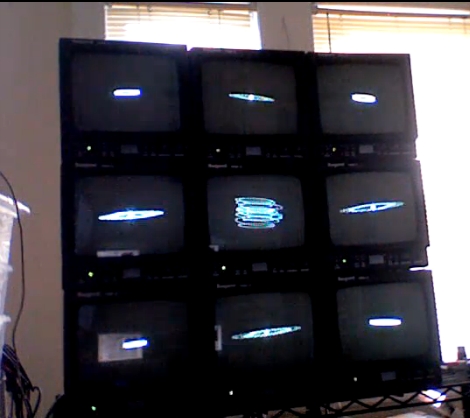
[Andrew] sent us a video of his home made oscilloscope wall, which he uses to visualize different audio tracks he has created. The wall is made up of nine old broadcast monitors he wired together in his studio. At first it appears that the monitors are split into two sets of four, with the center monitor running separately, but upon further inspection it looks as if he can control the display of each monitor independently.
We’re pretty sure he is not using an actual oscilloscope to generate the visuals, but rather visualization software that can approximate the output of an O-scope set in X-Y display mode. Though the screens run independently, it would be great to see all nine screens working in concert to display one large visualization. [Andrew] mentions that an high-def version is in the works, so perhaps we’ll see more features added in that iteration.
Stick around to watch a video of his oscilloscope wall in motion.
[youtube=http://www.youtube.com/watch?v=b-1zF0ofqRk&w=470]


Given that those are all CRTs, I strongly suspect that he is neither using a ‘scope(in the conventional sense) nor using any software.
Open a CRT TV: notice the X and Y control yokes around the electron gun’s beam path. Notice that the two yokes are just electromagnets with two pins running to the mainboard. Pull the plug out, shove your amplified audio signal lines in: one channel handling X, one handling Y.
The result is rather crude to be called an “oscilloscope”; but the hack takes about 5 minutes and requires no software at all.
(extra time will, of course, be required if you actually care about the well-being of your audio amplifiers. CRT control yokes are approximately similar to speaker coils in terms of impedance, in the sense that they are unlikely to either instantly catch fire or instantly frag your amp; but long term health is not assured without considerably greater attention to good analog design. Given the the approximate market price of a shitty set of amplifiers integrated into a tape deck or something is ~$0, this step is usually skipped.)
Crazy, I started doing exactly this yesterday. I’m with phisrow, I’m sure this is done in hardware. With a bit of work you could make it into a reasonably useful oscilloscope, it’s just a matter of feeding a ramp signal into the X and your test signal into Y
Magnetic deflection coils are probably fine for something like this, but it’s hard to make a good ‘scope with them because of their non-linear response. Real ‘scopes use electrostatic deflection.
You can also get a more “scope-like” output by swapping the vertical sweep to the horizontal coils and applying your signal to the vertical coils. The resulting 60hz horizontal sweep is reasonable for viewing audio frequencies.
Much fun to be had! Just watch out for the HV…
seems like he just has four of them to the left speaker channel and the other 4 to the right and the middle one a combination of the two? if you were to mix the music in w/e desired fashion with this being the medium for the art you would get those types of patterns.
Reminds me of an O-Scope in X-Y mode…
But anyways hooking up audio to the deflection coils isn’t really new. But this setup is definitely awesome. Not sure how useful it actually is, but as a visualizer I find it awesome!
I was impressed as was the judge at high school in 1970, but this is to the `nines’. Deff yoke drive.
when i was a kid in the 80s i would get b/w tvs for free or cheap and make (lissyscopes)like these all the time for myself and friends.It looked great when hooked to a stereo, but didnt last very long before the center of the tube got burned, but they were super easy to build.
beautiful.
people, please stop: we know how easy is to build a fuckin oscilloscope out of crts..
but this is something else