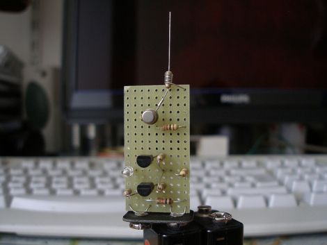
Who needs a Fluke high voltage detector when you’ve got one of these things?
Actually, we still recommend a professional high voltage detector for serious work, but you’ve got to like this electric field detector that [Alessandro] recently put together.
The detector works by using a JFET to detect the high impedance electric fields that are generated by high voltage lines. The JFET amplifies the signal while dropping the impedance in order to drive a pair of NPN transistors which are used as a threshold amplifier. Once the voltage hits 3V, an LED is lit, indicating the presence of high voltage near the detector’s probe. A wire-wrapped resistor does double-duty serving as the probe while providing a high impedance path to ground, ensuring that stray charge does not accumulate on the JFET’s gate, causing false readings.
It’s a neat project, and something that can be constructed in no time, making it perfect for beginner electronics classes.
Keep reading to see a quick video of the HV detector in action.
[youtube=http://www.youtube.com/watch?v=Pp0A6QvwqQE&w=470]


Kraus’ textbook “Electromagnetics” has a similar circuit for detecting atmospheric potentials and can be used to observe lightning discharges by putting the probe up high on a pole or chimney.
i build something very similar this morning before this project was posted. I used a schematic from the first book of transistor circuits from talkingelectronics.com
it uses 3 standard npn transistors, instead of 2 and the jfet, so is even more suited to beginners making stuff using junkbox bits!
Cool. I like the leakage gate resistor, a diode pair might work just as well and protect the input a bit more too.
Personally I’d redesign it for ultra-low quiescent current and 3V supply so it might be rendered into a keychain form factor with no power switch.
Maybe a complementary pair monostable biased close to triggering and just the front-end JFET standing a few microamps with capacitive coupling into the monostable?
I have a graphite fiber tripod, and for some reason, whenever I am near high tension wires, it feels differently. I can literally feel some kind of process going on when I slide a finger along the tripod – its a 60 Hz – …something…
My wife can’t feel it, I do. Its very noticeable. Anybody have any idea what’s going on, or experience something similar?
Also, in the UK, I think, there is an artist who creates installations under high tension wires with grid-like arrays of flourescent tubes.. In that heavily energized a location, they flicker without being connected to the “mains” as they call it. Its eerie..
Chris, carbon fiber tends to be conductive, I’ve no doubt that there could indeed be some induction happening.
I seem to recall there being a few cases of someone fishing near a high voltage line getting a slight case of the death when his carbon fiber fishing pole got a bit too close to the power line.
I sometimes enjoy stringing transistors together in a darlington configuration. Just touching the base of the first will light an LED for a minute, much like a mosfet.
we used to use a bulb in some fish tank hose. I think it was florescent or neon… it would glow orange when you got it near the fly back transformer on a tv.
Using a FET to detect static has been around for a while, see – http://amasci.com/electrom/e-field2.html for a simpler version.
I’ve never had the enthusiasm to build a display like that though.
I don’t get it. What is the purpose of TR2 there?
I love it!
It needs a nice analog meter though, don’t you think?
Wouldn’t that give a more dynamic readout than a simple on/off LED, or am I misunderstanding?
couldnt you use this as an emf detector for ghost hunting?
Only if you’re after the ten thousand volt ghost.
I’m the author, a few notes to comments:
1) if you are after ghosts, JFETs are the answer, BJTs are out, so this circuit might be what you’re looking for…
2) the LED blinking in the video is due to camera frame or CCD scanning while heterodyning with the LED flashing at 50Hz, sort of.
3) The purpose of TR2 is now explained at the bottom of my post.
4) For an analog meter, just replace R1 with 10k Ohm and place an analog meter (1mA f.s.) between V+ and Drain of FT1. Remove R3-R7, TR1, TR2, LED.
Ciao.
Ale
Hello Alessandro,
The site “5volt.eu” is no more accessible. Do you know where your article about the “high voltage electric field detector” could be accessible?
Thanks, Christian.
Almost forgot: if you are connecting the input to a high pole to detect static in the air, you definitely need protective diodes like Alan Yates (above) suggested (at the gate, after R1), otherwise your JFET will not last long!
Again, ciao
Alessandro
Original post dead link.
Thoughts on HaD adding a “graveyard” for old posts where the post reference is 404’d?
I second the graveyard idea. Maybe you can add the old junkbox section of the site that noone ever used to it.
Useless. Initial link is dead. AND? Spoofed “Flash Update” !
Does anyone have the schematic for building this with a parts list?? Building for a emf ghost project.
can you share the schematic circuit for this project…currently i’m working on emf ghost detector …please
seems the schematic is here: https://upverter.com/Vick77/0000000000006701/High-Voltage-Electric-Field-Detector/
i totally like it .Im also presenting a projeat like that one just give me the different typd of transistors like JFET & mosfet
Link is available in the web archive:
https://web.archive.org/web/20110605202731/http://www.5volt.eu/archives/207