Microcontrollers are digital devices at heart. They can do fancy things like convert analog signals into a digital value but going the other direction is a bit tougher. Pulse-Width Modulation is used to approximate an analog output but what you’re actually doing is turning the operating voltage on and off very quickly to achieve an average value somewhere in between. This is the method most commonly used to dim an LED. But generating a smooth voltage in this way takes just a few more parts.
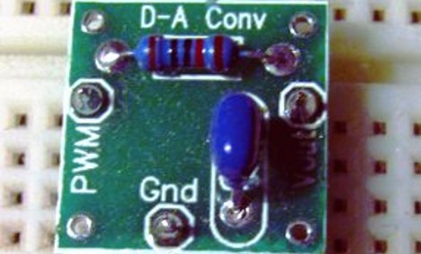
[Scott Daniels] spent some time discussing the process of smoothing a PWM output by using a low pass filter. This is a compilation of digital and analog circuitry to produce a smoother signal than PWM can achieve on its own. As you can see above, the low pass filter is made up of one resistor and one capacitor. The theory is not hard to understand, and with [Scott’s] help you’ll become much more comfortable with choosing the component values for your own filters. His examples center around an Arduino using the analogWrite() function but the techniques can be applied universally.


As a (primarily) self taught n00b to electronics, i find this VERY helpful!
frito
“They can do fancy things like convert analog signals into a digital value but going the other direction is a bit tougher.”
-> Actually, this is wrong. “Going the other way around” is actually harder. It requires more hardware, not mentioning that an ADC needs a DAC in order to properly convert that voltage to a binary code.
I usually enjoy these tutorials even if I’m comfortable with the topic. As is the case here, never filtered a PWM but I’ve done a lot of signal processing.
This tutorial is… useless? The focus is in the wrong area AFAIC. Thought Frito seems to appreciate it maybe I’m too far out of the target audience.
couldnt you just use a capacitor like you use in a power supply to smooth the output?
@ejoness the its a low pass filter, it makes a RC circit. in the PWM case the resistor makes it more responsive.
Thanks for this knowledge!
Well, I was going to comment that the incoming hacks may be slow… but based on the comments above, please continue iterating through all of the beginner concepts.
Or just post a link to this website:
http://www.allaboutcircuits.com/
Do not use this for mosfets like he explains in his examples. Sure mosfets use voltage on the gate to control the flow of electrons rather than current like a transistor does. However the whole point of PWM is to hit High and then Low without a long transition in between. By “smoothing” out the signal you are keeping the FET in its linear mode creating a lot of heat and you will eventually destroy the component.
Do 2 components REALLY need a PCB to be bread-boarded?
@Scott – Of Course! Where else are you going to put the labeling?
take it a notch higher with a 4 pin trinary weighted resistor dac
so, 4 pins = 4 trits = 64 different values.
ex:
high = 5v
low = 0v
high-z = 2.5v
drive each of the 4 pins with a 1k voltage divider (50% V) before you plug their output to a weighted resistor DAC. (10k,20k,40k,80k)
use opamp in a non-inverting follower config to preserve DAC current integrity.
check uC datasheet for high-z impedance.
Steer clear of the Health tab on that person’s website. It’s full of nonsense snake-oil medical advice that will hurt you.
@Scott
That was the first thing I thought of when I saw that.
@TheCreator:
There’s nothing wrong with operating MOSFETs in the linear region, this is how mosfet amplifiers/opamps work. If your FET overheats there’s something wrong with your component selection or amplifier design.
@TheCreator: MOSFETs ARE transistors, moron. We know several different types of transistors.
And no, your FET isn’t going to overheat and die if you are keeping it in the linear region. If yours fry, that means you suck at designing circuits.
@icept & @Myke – you guys are pretty critical about TheCreator’s wording and comments. I tend to agree with him in that the usage of a MOSFET to control LEDs as the author states in his article, is non-standard. If you want to limit current to an LED, you just fix the supply voltage and throw in a calculated resistor. If you want to make a constant current design you can use two resistors and two Bipolar Junction Transistors. You can also interface to both concepts to turn the LED on and off typically without any other components. You could also use an LM317 and one resistor, and so on.
Bottom line is there are a million ways to accomplish the same thing… try to be less attacking… it’s not an attractive quality.
I bet you might think I’m sexist because I assumed TheCreator is male, so if you want to let’s have a big long discussion about it.
You might want this for dimming high power LEDs, but if you regulate a motor via PWM, you want rectangular waves since the spikes have the highest torque to keep it running at low speeds, or get it running at all with low duty ratio. If you smooth out too much you could use a linear voltage regulator to start with.
@icept and @Myke, It depends entirely on what you are doing with the MOSFET. If you wish to do anything at all power conscious such as use it as a switch in a DC to DC converter then you definitely wish to stay in the linear region as little as possible.
Sure the FET probably won’t die if if biased like this but then you also don’t need one capable of dissipating quite as much heat giving you a very wide range of selection. For the most part for instance you wouldn’t use the same FET in a power amplifier as you would in a 5V buck switching regulator.
Arguing one way or the other is completely disingenuous. The point is that on the whole best practice is that unless you’re trying to amplify a signal you don’t want to operate in the linear region as it’s a horrendous waste of power for most applications.
Ha! I’m glad to find this post; it was very helpful today.
This way it still leave a bit of noise in the 50 – 100 mv region, is there a way to smooth that out to lets say 10 – 100 micro volts
You can use a PWM ‘tweak’ to avoid these extra components, you are able to set PWM frequency.