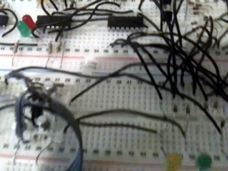
[TBJ] is building what he calls a junkbox 3D printer. You can probably guess that he’s trying to salvage most of the parts for the device, and after pulling a stepper motor from an old printer he was in need of a way to control it. What he came up with is a stepper driver that uses discrete components that are easy to acquire and inexpensive. The design calls for two inputs, one that toggles the direction in which the motor will spin, and the other that triggers one step of the motor. A CD4013 dual flip-flop takes care of both of these inputs in one chip package.
The motor is driven by a pair of H-bridges that he built using six transistors each. The trick with a stepper motor is that you need to drive the four poles of the motor to a specific logic level at a specific time. For this [TBJ] uses a CD4017 decade counter. A network of diodes grounds half of the output lines based on the flip-flop that controls direction. Our friend the 555 timer provides a clock for the circuit, keeping everything moving at a predefined rate. Check out the video after the break for an explanation and demonstration.
[youtube=http://www.youtube.com/watch?v=Y2fGj9A0MQI&w=470]


Nice, for once something where Bi-Polar and Girlfriend are not in same sentence lol. Interesting design….
I played around with a design a few years back. I used EMC2 to perform the indexing. His solution is much more elegant than what I attempted to do…
http://media.adamziegler.net/cnc/electronics/uni_step_drive_6-5.png (Dont laugh too hard)
just in time , have have been procrastinating designing such a circuit for a while now.
I gave it a good laugh when i read about shorting some outputs to ground… the design is poorly made, i don’t understand why he didn’t go for one of the popular designs out there. There are some built around a 4028 and some other logic ICs. Please, don’t tell me they need to be salvaged, they are dirt cheap.
You could probably save some space in this design by eliminating the second set of 8 diodes coming from the 4017 outputs. All you would have to do is move their connections to the other side of the existing diodes. I’ve worked with the 4017 IC when I built a kequencer, and they are only needed to protect the chip. Nothing more, nothing less.
This could be done simpler with one 74HC86 (quad XOR) and 74HC74 (dual D flipflop). Use a 555 for the stepping pulses. Offcourse the 74HC74 outputs need to be buffered with an ULN style octal darlington.
But still, different take on a common problem. Using a counter is nifty. I wonder if its 4 clocks per step or 8?
@Roman Dulgarov: Hahaha ;-).
I’m sorry, but this is just a horrible design.
Not only is it overly complicated, but it’s a real misuse and abuse of the logic elements.
(I suspect that it doesn’t even do what the author thinks it does in the manner he thinks it does it.)
There are many inputs with 1Mohm resistors to ground, that are totally unnecessary.
If the pin should be grounded, then ground it.
If the pin is driven by a logic output, then the 1Mohm is unnecessary.
The one place that there SHOULD be a 1Mohm resistor is the Clock input of IC2b, but it is missing. When the Step switch is not pressed, it is a floating CMOS input. Bad news there.
The Enable input on IC1 is floating, that’s another problem.
What is the purpose of the diode from IC1 Output_9 that goes to IC2b_R input?
The diode network is a kludge and shorting CMOS outputs to ground is a design violation. This is a really messy way to achieve the desired drive waveform.
A timing diagram would have been helpful, as I suspect that the operation in the Clockwise direction is probably distinctly different than from the Counter Clockwise direction. Based on the way the outputs of IC2a work, it is probably unnecessary as well.
There are many circuits for driving stepper motors published on the Internet. There is no reason to re-invent the wheel, but if the author was attempting to provide a new feature or novel implementation, I just don’t see it.
Hi everyone,
Thanks for the comments – to be honest I wasn’t really expecting that this would make it to HAD, but it has, so…
All good points made by Nate in particular – this circuit was simply a way of achieving something using only the parts I had around the house. I do realise, on reflection, that it has some design flaws and I will be taking all these things into consideration when reviewing the design.
However, what I would say is that a) it does work, and hopefully may be useful at least as inspiration for someone else who wants to achieve this, and b) it is my first attempt ever at scratch-designing an electronic circuit.
Again, thanks for the constructive criticism; it’s good to see this up here and hopefully whoever does want to build the circuit will take Nate’s very important points into account before making the decision.
Anyway, I’d like to close by saying that it was conceived as a hack, and it is a hack, albeit an ugly one :)