Controlling A Counter Top Water Distiller With Salvaged Parts

distiller_power_off_timer

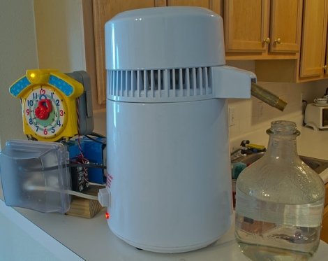
Hackaday reader [Kyle] wrote in to share a project he recently wrapped up, involving a counter top water distillation unit he uses at home.

He lives in Atlanta, and hates both the taste and contaminants in the water, so using this distiller is an absolute must in his house. The problem with this cheap unit is that it waits until it is completely dry before shutting off the heating element. According to [Kyle] this brings up two huge problems.

First, letting the unit run dry simply vaporizes all of the contaminants that he was trying to remove, allowing them to re-condense and contaminate his fresh water. Second, the heating element reaches extreme temperatures once the water is gone, which causes premature failure of the distillation unit.

He originally used a timer to remind himself to turn off the unit before it ran dry, but the process became tedious. He found that he would often forget to turn off the distiller before it ruined his newly cleaned water.

Looking for another solution, he decided to automate the process using some components left over from an Arduino-based terrarium temperature/humidity controller he built a while back. A salvaged toy clock tower was used as an input dial, which sets the distillation time on the microcontroller. The Arduino in turn manages a set of relays that controls the power supply to the distiller.

While [Kyle] only sent us this information to us via email, he has made code and pictures available online. We’re sure he would be pretty open to answering any questions you might have related to his build, so fire away in the comments section.

[Update]
After seeing that his distiller made the front page, [Kyle] directed us to a write up he prepared, detailing some more specifics on the project.


Computer-controlled EL Wire Light Show

starlight_parade_float_el_wire

[Paul] wrote in to share a project he recently helped assemble, a huge rolling light sculpture with a ton of computer-controlled EL wire circuits. The sculpture recently featured as a float at the Starlight Parade held in Portland, Oregon.

Working alongside the folks from Hand Eye Supply, [Paul] helped design and build all 114 of the float’s electronic circuits. Almost 1000 feet of EL wire was used to light the massive float, all of which was controlled by 15 Sparkfun sequencer boards. The boards ran custom firmware he created in order to communicate with the lighting software that was chosen to run the show.

In the end, the float came out quite nicely, but it was not without its problems during the construction phase. [Paul] ran into tons of issues when using Sparkfun’s EL wire sequencers, and has put together a detailed list of corrections he made to the boards in order to get them working properly.

If you are interested in learning more about the project, you can check out this behind-the-scenes look at the float’s construction.

Running Android On Large Touch Screen Displays

32_inch_android_touch_screen_display

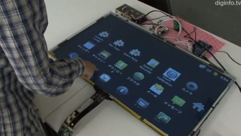
Forget Microsoft Surface, what do you think about having a 32-inch Android-powered touchscreen display in your living room? That possibility might not be too far off, thanks to the engineers over at SKR Technology in Japan.

Primarily a company that designs and builds digital signage, they were approached by several customers who wanted a large screen device that had multi-touch functionality similar to a smartphone. Since they frequently work with Windows, they tried building a solution around Windows 7, but it just didn’t function as smoothly as they would like. Instead they turned towards Android, but were disappointed to find out that none of their suppliers supported the OS.

Instead of scrapping the project, they build their own interface that allows an Android-powered device to interact with multi-touch displays. As you can see in the video embedded below the display works quite well, mirroring everything on the Android device’s screen.

While the product is not yet available commercially, we should see it come to market later this year. We hope to see an open source version sometime in the future as well, even if we can’t quite afford a 32” touch panel display.

Continue reading “Running Android On Large Touch Screen Displays”

Crafting A Hexapod With An RC Controller

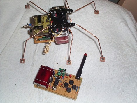
Here’s a fantastic project that lets to drive a hexapod around the room using an RC controller. [YT2095] built the bot after replacing the servo motors on his robot arm during an upgrade. The three cheapies he had left over were just begging for a new project, and he says he got the first proof-of-concept module put together in about an hour. Of course what you see above has gone through much improvement since then.

The three motors are epoxied together, with the one in the middle mounted perpendicular to the motors on either side of it. Those two are responsible for the front and rear leg on each side, with the third motor actuating the two middle legs. It’s a design we’re already familiar with having seen the smaller Pololu version. You might want to check that one out as there’s some slow motion video that shows how this works.

[YT2095] added control circuitry that includes an RF receiver. This lets him drive the little bot around using a transmitter with four momentary push switches on it. We love the idea of using copper clad for the foot pads.

Building A Stepper Driver

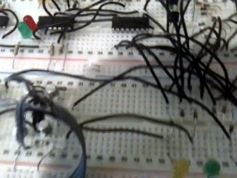
[TBJ] is building what he calls a junkbox 3D printer. You can probably guess that he’s trying to salvage most of the parts for the device, and after pulling a stepper motor from an old printer he was in need of a way to control it. What he came up with is a stepper driver that uses discrete components that are easy to acquire and inexpensive. The design calls for two inputs, one that toggles the direction in which the motor will spin, and the other that triggers one step of the motor. A CD4013 dual flip-flop takes care of both of these inputs in one chip package.

The motor is driven by a pair of H-bridges that he built using six transistors each. The trick with a stepper motor is that you need to drive the four poles of the motor to a specific logic level at a specific time. For this [TBJ] uses a CD4017 decade counter. A network of diodes grounds half of the output lines based on the flip-flop that controls direction. Our friend the 555 timer provides a clock for the circuit, keeping everything moving at a predefined rate. Check out the video after the break for an explanation and demonstration.

Continue reading “Building A Stepper Driver”

DIY Clock Replica Is Better Than The Real Thing

diy_tix_clock

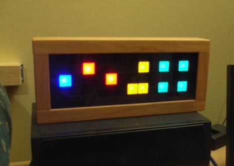
After seeing the TIX clock for the first time, [Gweedo Steevens] really wanted one, but wasn’t interested in paying the seemingly high asking price over at ThinkGeek. He figured it wouldn’t be too incredibly hard to build his own, so he decided to give it a shot.

The clock relies on 27 LEDs to display the time, which were multiplexed to make the most of his ATMega16 microcontroller’s available IO pins. Once he was happy with how things functioned on breadboard, he migrated the LEDs to a piece of perf board, and etched his own PCB for the controller circuit.

He used an office overhead lighting grate to separate the LEDs, providing nice uniform light segments. He put a piece of clear perspex on the front to cover the LEDs, but later switched it out for a much darker piece, for better daylight viewing.

The finished product is fantastic, and in our opinion looks even better than the retail version – awesome job!

[via HackedGadgets]

LED Wand For Light Painting Photography

[Michael Ross] is a photographer who has been getting into light painting recently. He’s come up with his own RGB light wand to create some amazing images, and also written a very, very thorough tutorial (PDF warning) on how to build your own light wand.

The light wand is based on an Arduino Mega board and uses an RGB LED strip based on the HL1606 controller chip. We’ve covered these LED strips before, and they’re very easy to use with the requisite library. So far, [Michael] has built a 48-LED light wand and a 16-LED wand with a 6-position program selector, making it easy to do awesome single-exposure photos like this.

[Michael] creates his images in an Excel spreadsheet – rows are which LED to address and columns are units of time. The picture data is then copied and pasted straight from the Excel worksheet to the Arduino source code. This in itself is a pretty clever use of Excel.

Check out the how [Michael] creates one of his light paintings here.