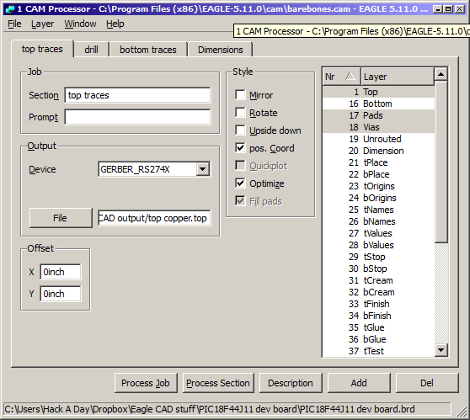
Here is the next installment in our series of Eagle CAD videos. In this video we skip ahead a bit and show off the CAM processor that you use to create the files necessary to have your circuit boards be manufactured. After watching this video, you will know how create a new CAM program, load a circuit board into the CAM processor, tell it where to save your files, and actually use it to create the files.
We’re skipping ahead today because of a screw up on our part. We meant to show the layout portion of the program today but edited the wrong video… We’ll show layout next week. After that, we will show the completed circuit board and solder the parts onto it.
If you are itching for some Eagle CAD layout info, you may be interested in some supplementary videos that we have uploaded to our Youtube channel. In those videos, we show how to use the most important features in the layout portion of the Eagle CAD.
Have you missed the previous videos? Here are some links to them:
Schematic and the beginning of a custom part: [click here]
More custom part stuff: [click here]
Video is after the break:
http://youtu.be/yJQUImv-gq8


I needed this a few days ago! oh well.
Btw there isn’t any good online tutorials for doing more than 4 layers, I ended up figure it out on my own after trial and error.
Nice video tutorial!
(Any chance you could post a tutorial on how you went about recording and editing this one?)
regards,