We got a lot of really great feedback about low battery cutoff options in the comments section of Monday’s replacement battery post. To refresh your memory, some power tool batteries were replaced by Lithium Polymer units which can be damaged if drained too low before recharging. We had thought that many Lithium cells had cutoff circuitry these days. The consensus is that these batteries didn’t because they’re for RC applications where weight is an issue. But we did get a ton of people sending in commercially available drop-in solutions, mostly from RC hobby outlets, so search around for those if you’re interested.
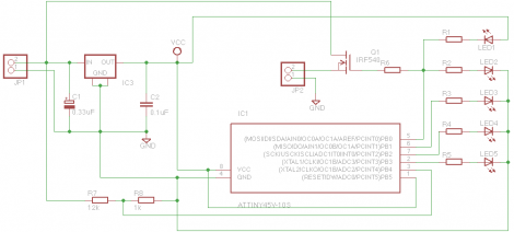
[Christopher] sent us a link to the cutoff circuit he built for his bike light. You can see the schematic for it above (direct link). He sourced an ATtiny45 to drive a MOSFET which disconnects the battery when it gets too low. This would be easy to adapt to other uses, but note that there’s a voltage regulator involved as well as a few other passives… not a difficult solution but also not all that simple.
This same concept can be adapted. A few commentors mentioned using a transistor (or MOSFET) with the base driven by a voltage divider including a zener diode. This way the voltage rating of the diode would effectively shut off the gate when that threshold was reached.
We also enjoyed reading about [Bill’s] human-controlled cutoff circuit. It also uses a zener diode, but this time in series with a resistor and and LED patched into the trigger of the tool. The LED will shine brightly when the battery is in good shape. It will dim near the end, and fail to light when the critical limit has been reached. Just make sure you’re paying attention and you’re in good shape.


That is actually a nice one. I will consider using this for my carpc setup to build a backup power source, because ignition seems to reset the present radio, which i think will also happen to the carpc when without a backup. Also this would make the whole thing resistant to sudden voltage drops. (Note: a pandaboard will be used).
Though i think i would change a little thing about this: I will provide the circuit with a second fairly small power supply, so the whole thing doesn’t use the LiPo, when in red state, so i can cut off the LiPo completely instead of draining more power off it with the red LED and the voltage regulator.
You can always mod the code to go completely dark when at ‘critical’ level (or blink infrequently).
all those solutions still have some quiescent current – I think a ‘real’ low voltage cutoff would perhaps keep a relay juiced and switch it off, breaking connection to the battery, when voltage gets low.
This is a great simple solution.
Does it work for Lithium batterys?
I could use a Op-Amp to amplifly my 3.7V battery into 5V, and connect it to a 5V relay.
Will it work?
Thanks a bunch!
Sure, as long as you don’t mind losing battery power to keep a relay energized.
“This way the voltage rating of the diode would effectively shut off the gate when that threshold was reached.”
The transition isn’t exactly sharp, driving a MOSFET gate directly out of a voltage divider, because you will go from full saturation to partial saturation where the MOSFET will be halfway open and that will reduce the current to the load, which will see an increase in the voltage… etc. etc. you get the point.
That is saying, that once the MOSFET starts to shut off, it will find a balance point where the MOSFET is dissapating power to regulate the load to keep the voltage up, which means that A) you need to set the saturation point way up to not undervolt the battery, and B) given A, you will lose torque from the drill as the battery nears empty, and C) you may burn the MOSFET.
You basically need a comparator, or a simple darlington transistor switch to provide a sharper cut-off for the MOSFET.
Of course if you use a heavy duty MOSFET and add a proper heatsink to it, you can use it as a current limiting switch when a certain voltage level is reached.
The sharper cut-off means that once the battery starts to go empty, and you load the motor, it will start to oscillate because the MOSFET cuts the power off every time, so you know your battery is empty when the drill starts to buzz in your hand.
Hitachi has done a great job with battery maitenance on their drills. I own a set with Lithium batteries and although the sudden cutoff is annoying (no notice the battery is about to die) it’s also nice to know that regardless of the battery level I get the same consistent power throughout the battery life (which is actually a very long time). As long as I keep a battery in backup the sudden cutoff isn’t a problem.
Texas Instruments makes a wide range of battery management chips. I know its a hacker community and all, but why are we wasting time reinventing battery protection?
http://focus.ti.com/paramsearch/docs/parametricsearch.tsp?family=analog&familyId=411&uiTemplateId=NODE_STRY_PGE_T
Heres one I randomly found that does over/under voltage, over current, and also gives you an accurate % remaining on your battery. It costs $3 normally but you can get free samples.
http://www.ti.com/product/bq28550
Three parts: Wire an LED, relay coil, and trimpot in series. Connect them after the on/off switch, across whatever load the battery pack is powering. Connect the relay’s normally closed contact in series with the load.
As the battery voltage falls, the LED dims as a warning. When the voltage gets low enough, it can no longer pull in the relay, so the load can’t be powered. Adjust the threshold with the trimpot.
Zero power when off. Zero voltage drop to the load when on. Will let you finish that “one last hole” once started, but won’t start again.
Oops…. normally OPEN contact. :-)
It’s been done, and done well; a single SOT23-6 part, and a couple of common SMT FETS will do the job:
http://datasheet.sii-ic.com/en/battery_protection/S8241_E.pdf
88 cents at Digikey
Remember the application here is a power drill or headlamp maxing out a 3 cell LiPo pack at something like 60 watts.
A chip designed to monitor and regulate 500mA from a phone battery is going to make a pretty puff of blue smoke, briefly.
There are plenty of cheap and easy charge monitor and protection chip for single-cell situations. I didn’t find any that gave a simple analog state of charge graph for multi-cell packs, hence why I designed this circuit.
RC Packs do not use the circuit because of worries about weight, it is because you dont want your $1000 airplane or helicopter falling out of the sky because the pack suddenly shuts down for some reason. Better to destroy a $50 battery pack than loose the model.
exactly, the wires on the battery weight more than the circuit to shut the power off.
Remember undervoltage is only *one* fault condition for lithium chemistry. Decent battery packs often contain a module with an IC, like the ones posted above, to protect against them *all* faults.
While you could incorporate protection against each fault separately, or build your own module from a bare IC, you can also buy pre-built modules. To post an example:
http://www.amazon.com/Protection-Circuit-Module-Li-Ion-Battery/dp/B0021ZN8WY
Search Ebay for “battery protection circuit” for a lot more examples, in many different configurations. $3.95 shipped for a tiny one that fits directly on the end of a single 18650 lithium cell. Or ones for up to twelve cells in series, that perform charge balancing as well.
You might also be able to salvage these modules from old battery packs too.
Really you just need a zener diode of an apropriate vaule tied to an adc PIN, then just measure different voltage ranges or just the voltage you want to cut off at, and becareful with multiple cell packs such as 7.2v, 11.1v and so on, so that you don’t over discharge one cell.
[Christopher]’s Attiny45 solution uses a voltage divider and ADC pin to sense the voltage. I just finished a Attiny25/45/85 project that uses a nifty trick to sense the voltage without using a pin at all. Ibrahim Kamal writes about it here: http://ikalogic.com/band_gap_avr.php
Basically you measure the internal bandgap reference voltage of the Attiny/Atmega using the ADC. The internal reference stays constant while VCC changes, so with a dropping VCC the ADC will read a higher value. If it’s above a certain value, that means VCC has dropped too low. Just cut the power to the rest of the circuit and put the AVR to sleep to save as much power as possible.
why not just have a comparator? band gap reference on one end, resistor divider on the other. when the voltage goes below the threshold, the comparator triggers.
If you don’t want to discharge the battery entirely, discharge it through some diodes or some LED’s, the battery terminal voltage will never fall below the forward drop across the diodes or LEDs.
Hi guys, really… MASSIVE thank-you for posting those links. I’m still a novice at electronics and have been held up by this exact issue on one of my projects for a very long time now.
Quick question though, some of those ebay ICs allow the battery to drop to a really low voltage, some as low as 2.6v… Is that even re-usable after that point? Fair enough it will stop it fire-balling but will it not start to cut into the capacity at that sort of rundown? I’ve been basing my design on 3.1-3.3 sort of range for cutoff.
It’s generally considered that touching 2.5 volts makes the battery dangerous to recharge again.
I’ve designed a simple circuit to monitor and cutoff battery voltage when it gets too low, with a reset function that powers the circuit when a fresh battery is detected. It doesn’t use a micro and both the cutoff and reset voltage levels are programmable with a potential divider. I can dig up the schematic and board layout if any one is interested.
My standard UVLO circuit is just a comparator circuit with massive divider resistors and about 1% hysteresis controlling a low-side FET. You can even toss in a tiny LED drawing about 1mA to show that the UVLO tripped.
I’ve been googling for this for a while. I have a circuit (a usb powerbank) run by a protected 18650 but I want to add some external low voltage cutoff because:
1) 18650 protection board cutoff kicks in at 2.5-2.4V which i think is definitely too low for daily use
2) a protection circuit should be the last resort in case something goes wrong, i don’t think it should be used on a regular basis (and i don’t know how reliable they are)
It looks like a simple and common problem, but apparently the solution is not as simple. All the simple circuits shown in this posts or googling around (that’s an interesting one http://shaddack.twibright.com/projects/method_SimpleLiPolyOverdischargeCutoff/ ) have some drawback that made me discard them. So what is left are dedicated protection boards, as more than one suggested.
But again, a couple from the page linked above http://www.all-battery.com/1S_Li-Ion.aspx looks great, but that shop is a solution for people living in the us only. As i live in europe i’ve had a look to protection pcbs on ebay and aliexpress, cheap and easy, but i can only find circuits with cutoff at 2.5v or 2.4v while something around 3.0v is needed… if anyone finds something it would be much appreciated ;)
SO:
here’s my idea, both to share and to ask for opinions… since finding a board programmed for 3.0v cutoff seems too complicated, i thought to tweak the common 2.5 cutoff board that i can easily steal from a any 18650 i have laying around or just buy a bunch of them on aliexpress for as low as 0.50$ shipped or less:
http://www.aliexpress.com/item/New-1-5A-PCB-Charger-Protect-board-for-1-Pack-3-6V-3-7V-MP3-Lithium/32263803202.html
http://www.aliexpress.com/item/New-2A-PCB-Charger-Protect-board-for-1-Pack-3-7V-4-2V-18650-Li-ion/32222357093.html
Then I can use a voltage divider with just 2 resistors to set the kick in voltage wherever i want, instead of connecting the board reference directly to the positive electrode… of course resistors in the Kohm-Mohm range would be needed to avoid battery drain, and it’s probably a good idea to add a capacitor when using so high resistor values for the reason explained here http://jeelabs.org/2013/05/16/measuring-the-battery-without-draining-it/ (i don’t know much about microcontrollers, but i guess this high impedance thing might be a common issue).
Low battery cutoff is such a critical detail that’s often overlooked, especially in DIY projects.