[Claudio] was working on a homebrew oscilloscope project when he started thinking about how unsuitable a standard breadboard is for a large-scale project. Rather than adding components on top of components until they became what he lovingly calls a “fragile, unforgiving crapstack”, he decided to build himself the Ultimate Breadboard.
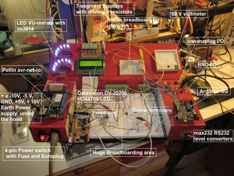
He packed so much into his design, that it’s honestly hard to know where to begin describing it. Aside from an appropriately large breadboarding surface embedded in the center of the console, he added a power supply to the left hand side, which sits just below an Avr-Net-IO board. The right side of the console features an Arduino NG, and a pair of level converters. He also added some LED-based VU meters, a couple of 7-segment displays, an LCD display, an analog voltmeter, along with plenty of I/O connectors.
The Ultimate Breadboard might look a bit daunting at first, but it seems like an awesome setup on which to do any sort of prototyping. Be sure to check out the video below for more details and to see [Claudio] give a tour of the device.
[youtube=http://www.youtube.com/watch?v=mQ7dO3iekb4&feature=player_embedded&w=470]


That is a pretty insane setup! :)
I have the PAD-234, it is a pretty sweet setup with much of what I need to do a quick breadboard. I always like a lot of proto space so I have several external boards as well. I went with the 234 because it also has a ribbon cable extender for ease of expansion.
His website returns “Error establishing a database connection”
Bummed
Yep. Looks like one of the little wires must have gotten yanked out of the breadboard.
Just put the wire back in :) the server should be up again.
memo to myself: Get a more powerful server!
I think I am in love.
Man, you guys just announced this, and the webserver fell over ALREADY ???
Big sad face… I wanna see the site…. :-(
Wow, i thought there would be a lot more replies on this one!!! Isn’t this a dream!!!!
You could look at google’s cached page, it takes a “crapstack” time to load though
The google cache takes a long time to load, but it eventually works:
http://webcache.googleusercontent.com/search?q=cache:VY9IVLMdb54J:www.amateurengineer.com/%3Fp
Above cache URL got chopped. Here it is again:
http://webcache.googleusercontent.com/search?q=cache:VY9IVLMdb54J:www.amateurengineer.com/%3Fp%3D400
Sorry about that, thanks
If your not as creative yourself, one commercial options is the Digilent EEBOARD, which has a nice oscope and function generator for the price imho.
For a bunch of EEs and ETs, you lot sure get things wrong!
A VU meter uses a vari-log scale that reflects the particular characteristics of the human ear. Hence, the term “Volume Unit”. The chip for this is the LM3916, NOT the linear-response of the LM3914, or the log response of the LM3915. So, what he has is NOT a VU meter, but an adjustable linear scale LED “orbital” bar/dot graph.
Yeah you are absolutely right, my original design had 3916s but I had none at hand so the 3914 went in. Just didn’t think that over.
Site down…
Slashdot teardown effect ? let’s call it hackaday massive visit effect :-)
Looks useless. Defeats purpose of breadboard
…why a long deprecated arduino NG?
Oh wait… the NG has a direct serial output doesn’t it? The newer ones rely on USB.
That’s the second sweetest thing after my granddaughter :-) I am going to build something similar, just smaller and with features I need. My wife will love that, she always complains about the mess on my desk, and this looks like something that could be easily stowed away.
Very sweet.
If it doesn’t already have it, I’d add a switch to each module, allowing it to be disconnected completely from the power supplies. Would be a shame if an accidental surge on a supply wipes out everything, whether it’s actively being used or not.
I build similar modules, but put them on 1/2″ aluminum standoffs with small supermagnets glued to the bottom. A piece of sheet metal is my prototyping area. When I need a module, it snaps securely into place anywhere I want it, and won’t easily slide. Wires can be routed under the elevated modules to reduce clutter at the surface, where you’re going to be doing the most work. Magnets/standoffs can also be attached to breadboards, battery holders, test equipment, etc. Makes for a very neat and flexible prototyping system.
One last suggestion – there’s a spring loaded version of those terminals, where you just push a tab to insert/release a wire. Faster for prototyping. Better for permanent projects that may be subjected to vibration too, since there’s no chance vibration will eventually cause a screw to back out. Only downside is they’re harder to find. Sparkfun has them. If you want a bunch it can be much cheaper to go straight to their supplier, 4UCON, which has almost any connector you can think of. They normally deal in large quantities, but you can buy a limited quantity of each connector as samples. For example, on one order you could get 10x 2-pin spring terminals, 10x 3-pin, 5x 4-pin, and so on. If you need more, just place another sample order. I’ve loaded my parts box with tons of useful connectors that way.
For those who would rather buy a pre-built solution… (none of you, I’m sure!)
http://www.edakit.com/article.php?id=7
Wow! Certainly almost perfect for Claudio, at the time he recorded the video anyway. As for the rest of hackerdom. Many may employ much of what we shown, other may see it as a waste of valuable bench space. In that regard, this needs some of the features mounted on a vertical back plane, although this build is suited for those who work stand up or sitting on a tall stool at the bench.
I hate to be the bummer here. But really, things are pretty spread out. It’s nice to have a lot of the things he has, but the long wires needed for a lot of it would negate most of it, unless you’re working at low speed and don’t mind noise on the lines (like the (non)VU meter).
Certainly has the right idea, but really, clean it up, and compress it all into nice, neat, small packages.
You can put several items on a single PCB. Make a few of those and you’re set.
Good idea though. I’m not knocking that, just it’s implementation.
And yet, it is still a rat’s nest of wires.
A breadboard like that would be incredibly unwieldy. I think that large projects are the best justification for wire-wrap.
In one case, when we had a big chunk of circuit nailed down, we did a prototype pc board and stuffed it, and used a flat cable to connect to the breadboard for work on the next part of the circuit.
Anytime ive ever prototyped something Ive always got a rats nest for some reason it a builders virus I think. Heck DaVinci probably had a rats nest of ropes and pulleys when he was building something