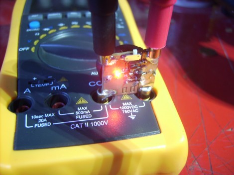
This multimeter add-on is called the Half Ohm. It allows you to measure small resistance values, and can be used to track down shorts on a PCB.
The board acts as a pass-through for both probes. When your meter is set to measure voltage and nothing is connected to the probes the display will read out the level of the coin cell that powers the add-on. When you are probing, the value in millivolts is actually showing the resistance in milliohms. This works for any measurement less than one Ohm. Interestingly enough, it will help you zero in on a solder bridge. By probing the two shorted tracks you can find the issue by following the falling resistance values.
[Jaanus] published several posts leading up to the final version of the board. Check out this category link for his blog if you’re interested in reading through them.


Why don’t they give a schematic for it? Seems like it goes against the open-source philosophy of HaD.
It does on the site?
http://jaanus.tech-thing.org/img/Half%20Ohm.zip
A strange philosophy: “everybody uses kicad, and has it installed”. What about good ole’ PNG? As the schematic is obviously small, even a single screenshot would be enough if that software is unable to export to raster formats.
saimhe:
Here’s a PDF version of the schematic:
http://www.sharepdfbooks.com/25UFDFX28C4J/Half_Ohm.pdf.html
They do! At the bottom of the page there’s a link for the kicad schematic
In the link, there’s a schematic in KiCad format, and in the “category link”, there is some theory of operation.
As for me, when I’ve needed to measure very low resistance, I’ve just hooked up a known current source, usually from a bench power supply, and then measured the voltage across the resistor with a known current going through it. Doing it this way, the probes to my voltmeter don’t carry significant current, so the probes don’t contribute to the resistance reading. That’s known as “Kelvin” or “4 wire” resistance measurement. If you don’t use the Kelvin method, then yes, it’s possible to zero out the resistance of the probe wires themselves, but it’s not so easy to eliminate the variable surface resistance of the contact between the probe tip and whatever it’s touching.
looks like a real useful tool.
It is very rare that I see a project on Hackaday that immediately makes me take my wallet out. TAKE MY MONEY ALREADY
http://diyaudioprojects.blogspot.com/2008/11/simple-low-resistance-measurement.html a method like Richard mentions.
The multimeter add-on idea is nice but the problem of this deign is that it also measures the resistance of the probes and probe contacts. That’s not negligible when measuring milliohms. A better design (but more complicated) would use 4 probes, 2 to supply current, and 2 to read the voltage drop.
Also known as Kelvin sense probes; good ones tend to be pricey (we just got a ~$400 set for the lab).
quit showing off…
very astute comment vic. keep it up.
-fartface
exactly vic. the ultra low resistance meter i use can measure down into micro-ohms. it also needs to be calibrated often, leads cleaned and well maintauned.
Sorta like my GenRad Bug Hound…
Useful in finding a shorted IC on a PCB by starting at the supply and following the rails to find the least resistance.