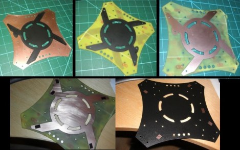
When working on flying vehicles weight is always a consideration. [Brendin] found a way to get rid of a wiring harness on his quadcopter, simplifying the assembly while lightening the load. He did it by incorporating the power bus into the frame of the vehicle.
He started with some copper clad board. Because the substrate is a structural component he didn’t want to use a CNC mill to do the etching as it also removes a bit more than just copper. After using the mill to cut out the shape and drill holes he coated the board with flat black paint. This acts as the etch resist, which he sent through a 50W laser engraver to remove the paint and expose the areas he wants to etch. After etching he removed the rest of the resist, and masked off his solder pads with small rectangles of electrical tape. This protects the solder pads from the truck bed liner paint he uses to insulate the copper. He says it works great and plans to use the technique on all future builds.


Id like to see the effects of the emf on the signal lines
There really isn’t as much emf on the power lines of ESCs. I was quite surprised when I probed one with a oscilloscope as the only variance on the power buss was some voltage drop when the motors are loaded.
Short lengths of piano wire are very stiff, slightly flexible, and conductive. Triangular shapes would be very strong.
I must say, what a brilliant idea !!!
not to steal your glory, here is one for a hexacopter :-)
http://diydrones.com/group/3d-models
Interesting that he is trying to save weight, but using bed-liner as an insulator. Why not Kapton tape or enamel paint?
And not a single word about how much weight was ACTUALLY saved.
If you read his blog he never says he was doing it to save weight.
… and yet the summary implies it was, with the first sentence.
very nice idea! i may end up adapting this to my raptor when i finally get out or the R stage and start doing some D
WHATEVER. my ~30cm of heavy-duty speaker cable connected in a circle and soldered to each esc at 3,6,9,12-oclock positions work just fine. it also took 12 seconds to make, and that includes getting up from my desk and reaching for the spool, and using hte side-cutters to cut it to the right length. Soldering to the ESC’s took another 90 seconds, but that doesn’t count, as the milled PCB has to be soldered too.
Sure, but this does make things look cleaner, and you don’t even have to worry about cable routing, which can be trivial or difficult depending on the chassis design.
Only hackaday mentioned the weight. It seems he actually did it to clean up the wiring harness
Someone should go the whole hog
and make a hybrid carbon fibre/
PCB wafer thin copter frame.
Don’t forget that 0.2mm pcb
weighs next to nothing anyway..
This isnt a new thing, DJI uses pcbs for their quad/hex copter kits and they use them for mower distribution too.
http://www.rchobbyhelicopter.com/store52/agora.cgi?product=DJI_Innovations
(Scroll half way down the page)
Indeed. Hobby King also sells frames using this same idea and have for some time.