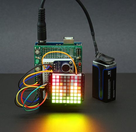
If you’ve ever wanted to make your own VU meter but were scared off by the signal process you need to study this tutorial.
Hackaday Alum [Phil Burgess] developed the device using an RGB LED matrix, microphone, and an Arduino. You’ll notice that is doesn’t include an MSGEQ7 chip which we see in most of these types of projects. We have seen a few that use the Fast Fourier Transform to map the audio signal on the display as this one does. But [Phil’s] choice of an assembly language Library for ATmega chips makes this really simple to roll into your own projects.
The one drawback to the hardware choices made here is that there are only eight bits of vertical resolution. It takes a little creative interpretation to make this look good, but the use of color mixing really makes a difference. See for yourself in the demo after the break.
[Thanks PT]


Most of the projects that use Elm Chan’s FFT library show a lot of lag and/or missed beats. This one looks slick as snot. Great work!
It’s not a friggin’ VU meter! Those are used to show AVERAGE overall audio level (a.k.a. volume): http://en.wikipedia.org/wiki/VU_meter . When you have multiple band-limited PEAK meters you get a http://en.wikipedia.org/wiki/Spectrum_analyzer
It does actually have less lag because it is using very few frequency bands..
This is true for the output bands. However the source code indicates they are performing FFT across 128 samples.
Actually you are right.
I found some stuff i build a long time ago, but i only have a movie. There apperars to be no delay there either. The display is a Siemens mobile phone one (SPI interface), the chip is an MEGA16 at 16MHz. Looks very instant, no delay.
I don;t remember what lib i used, but i remember it was mostly ASM.
This looks like 8 steps vertical resolution, which hardly amounts to 8 bit. I’d say approximately 3 ;)
Yay! 8 bins.
Not exactly an RGB LED matrix — there’s no blue, just red and green: Bi-Color 8×8 Matrix.
I would agree that the tutorial is awesome on the basic concept standpoint, but it would be far more awesome if it wasn’t just “Plug in this shield” and “plug in this backpack”. For the Arduino LED matrix shield thing, how is it only using 4 pins? Is there a shift register on there I can’t see? Is it charlieplexing or what?
Using pre-made hardware and libraries is far less instructional than having to learn/do it yourself. FFT is one of those things I can do if I reference a textbook the whole time, but it would be nice to understand implicitly.
How could you edit this code to work with ws2812 leds?