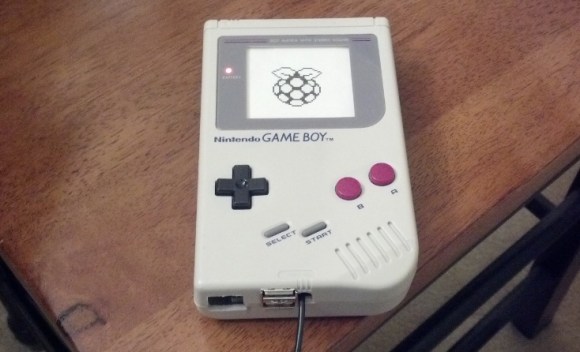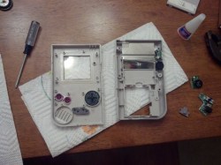
[Matt] still has his original Game Boy from when he was a kid. He wanted to pull it out and play some of the classics but alas, the screen was broken and he couldn’t find a source for a drop-in replacement. In the end he ordered a used unit and pulled the screen from that one. This left him with a pile of leftover Game Boy parts which turned into a Raspberry Pi case project.
Since the RPi doesn’t have a power switch he thought it would be pretty neat to incorporate the Game Boy power switch. He was able to cut out one section of the original PCB that included the switch and one mounting hole. This kept the switch aligned with the case and gave him some pads to solder the incoming USB cable and the jumper wires to the RPi board. In the image above the power LED is on. He mentions that there was an issue with that circuit; the voltage drop across the LED was messing up the feed to the Pi so it’s disabled for now.
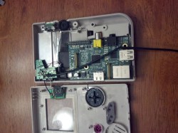
We’ve embedded a couple of images of everything inside the case after the break. If you’re a fan of this hack you should also take a look at the Game Boy hard drive enclosure which uses the same pixel art printed on paper effect for the screen window.


is the screen somehow connected to the raspi, or is it just a mockup?
“If you’re a fan of this hack you should also take a look at the Game Boy hard drive enclosure which uses the same pixel art printed on paper effect for the screen window.”
Seems like it’s paper.
Really a missed opportunity here to re-use the Gameboy LCD… :(
The LCD was broken, so he bought one basically for the LCD and had everything but the LCD. So what missed opportunity ;)
Missed opportunity to make the hack even cooler by incorporating an actual GameBoy LCD. Maybe not re-use, sorry.
It would be extremely hard to repurpose the original LCD, seeing as no one in the hacking and homebrew community has effectively reverse engineered it. The LCD contacts, roughly 40 of them, are hard wired to the front PCB of the Gameboy and require other chips attached to the PCB to drive it. Not to mention all the dependencies on the z80 CPU from which the screen derives refresh rate, etc.
This project failed to get proper funding, but it was a little more than just a boring case hack. http://www.element14.com/community/groups/raspberry-pi/blog/2013/01/02/uxeboy–a-gameboy-based-interface-to-the-raspberry-pi
dude get one of those $14.00 amazon.com backup camera screens and hook to the Composite out . Make that Gameboy actually work with the rasPi as a mame player.
I see so many hacks here go only 1/2 way, This can be epic, go shopping to finish it!
This.
Super friken awesome !!
Thanks for that!
I will want to make it epic!!^_^
i got one, completely unreadable, and much of the gui doesnt fit @ 640×480. i guess its ok if all your doing is playing roms.
Aw, I was hoping that the “screen” was an epaper diaplay. :(
He could have made it into a real gamboy emulator thing…
The GPIO for the buttons and a small screen from amazon.
Just de-solder the composite usb and power connectors. He could even fit a battery in there with a bit of work!
Like so:
http://www.element14.com/community/groups/raspberry-pi/blog/2013/01/02/uxeboy–a-gameboy-based-interface-to-the-raspberry-pi
Like so:
http://tinyurl.com/uXeBoy
I still have empty gameboy cases… I’m at least going to try this when I get a Pi, since I’ve been wondering what to do with them.
A lot of people suggesting to add a screen, but can anyone tell me what kind of screen is both small enough to fit, inexpensive, and can be driven by the Pi without a dedicated program?
I know there are many SPI and TFT displays, but none would work with an emulator.
I think its cool, but would have been a lot cooler if it was working as handheld gaming system that you could use mobile them plug it into a HDMI and use a Monitor and Bluetooth Key Board and Mouse.
How did you get the power light hooked up?