NASA Inspired Circadian Rhythm Lights

circadian-rhythm-light-rig

After reading about an initiative between NASA and Boeing to develop lights for the International Space Station [Rasathus] decided to give it a go at building his own. The project uses RGB pixels to build a circadian rhythm light installation. Without the normal rise and fall of the sun the sleep wake schedule for the astronauts can be pretty rough. This uses color and intensity of light in a well-defined schedule to help alleviate that. [Rasathus] is trying to bring his project in well under the $11.1 million mark which was established for the ISS.

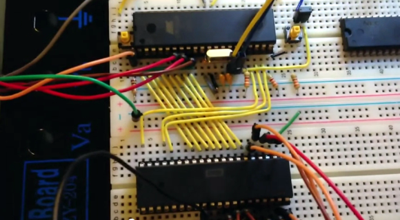
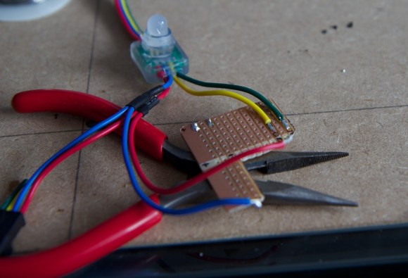
The light modules he’s using are from a strand of LEDs from Adafruit. Each is driven by a WS2801 controller, a common driver used for easy and complicated projects like this huge ball of light which our own [Jesse Congdon] tackled. The board above is the start of an adapter board for interfacing with the Raspberry Pi GPIO header. [Rasathus] wanted to make certain he didn’t fry the control electronics so he built some protection into this adapter. The control software is covered in the second portion of  the write up. We’ve embedded the video from that post after the break.

Continue reading “NASA Inspired Circadian Rhythm Lights”

Another Take On The 6502 Computer

another-take-on-the-6502-computer

[Mark] is just starting off on his own 6502 computer odyssey. He was inspired by some of the other projects we’ve seen around here, like [Quinn Dunki’s] Veronica Project, but with a spin that leverages modern processors to alleviate some of the messy work. As you can see above, there’s an Atmel chip perched above the 65C02 processor. This chip not only feeds the processor data (through all those slightly diagonal yellow wires) but also provides the clock signal and operates the reset and bus enable lines.

This is more of a hello world post for [Mark]. The chip is simply running NOP commands right now. But it shows that the basic idea works, and the video after the break lets us see another time-saving aspect of the circuit. He’s using a character LCD to display memory location and data values. The plan is to get a blog going, which he’s hesitant to do as it takes valuable hacking time away from the project. We disagree. The write-up (although incredibly fun for us to read) ends up being a reference manual for him once the project starts to get really hairy.

Continue reading “Another Take On The 6502 Computer”

SCARA Arm 3D Printer

scara-3d-printer

[Quentin Harley] must really have wanted to test his snuff when it comes to mechanical engineering. He’s been hard at work for a couple of years now designing his own SCARA arm 3D printer. That link leads to a recent summary article in which he shows off the build as seen above. It’s not fully functional yet, but he’s at the point where it’s time to develop the driver circuitry and firmware so he’s close. His blog is dedicated to this single project so click around and see what he went through along the journey.

The SCARA arm is seen in blue, using a couple of stepper motors to move the extruder mount along the x and y axes. The bed itself moves along the Z axis via two precision rods with a threaded rod in the center. As you can see, some of the parts are made of wood, and he used PVC for the cross supports between the upper and lower base platforms. But the majority of the build uses 3D printed parts, including the arms, drive gears, and mounting brackets.

[Thanks Peter]

A Pair Of Automatic Fish Feeders

a-pair-of-automatic-fish-feeders

Sometime the hacking topics come in waves. For instance, we were tipped off about this pair of automatic fish feeders just an hour apart from each other. Maybe it’s that time of year when people are about to go on Holiday and want to make sure their marine pets don’t go hungry?

The feeder on the left is a true hack. It’s built from a pair of servos and a pill bottle. An ATtiny85 drives the motors. One is mounted to the other, allowing the cap which catches and distributes the food to move along two axes. When it rotates into place under the pill bottle it bumps against a stick to open a flapper releasing more food.

On the right is a feeder that precisely doses the food. That’s because it includes a separate chamber for each feed. A worm gear drives the hopper, with screw heads pressing against a leaf switch for position feedback. This one is well designed and built to last.

Programming A 555 Chip

555

[Phillip] needed a way to trigger an input every 8 hours or so. This is a snap with a microcontroller with a proper timer, but he recently heard about a very cool programmable timer chip that’s also a 555. Of course CSS555 timer chip has an obscure programming interface, but that isn’t a problem when you can program it yourself with a parallel port.

The CSS555 timer chip (PDF…) is a strange little beast. It’s pin compatible with everyone’s favorite timer IC, but also has a programming mode that allows the output to trigger on every 1 cycle, every 10 cycles, and so on up to one output every million cycles. Basically, it’s a 555 with a huge programmable capacitor that only costs two bucks.

After building a programming circuit from a 74125 hex buffer chip, [Philip] connected his programmer to the parallel port of an ancient PC. For a little retrocomputing cred, he wrote a small app in Forth that pushes commands from the parallel port to the CSS555 chip, greatly increasing the time delay of the chip’s stock configuration.

It’s a neat build, and an awesome introduction to a really cool timer chip. Of course this could be easily replicated with a $2 microcontroller, but that wouldn’t give [Philip] the satisfaction of using a 555.

Building A Tool To Measure Melting Point

melting-point-apparatus

When working with chemical reactions it may be necessary to test the purity of the components you’re using. This is especially true with hobby chemists as they often acquire their raw materials from the hardware store, garden center, or pool supply. [Ken] figured out how to get around the $500 price tag of a commercial unit by building this DIY melting point test apparatus.

In this image he’s using a thermocouple to monitor the temperature of the melting surface, but mentions that you can do this with an inexpensive dial thermometer and will still have great results. That melting surface is the hexagonal head of a bolt which he drilled out to provide a concave surface for the test compound. Inside the PVC pipe is the heating element from a 40W hot glue gun. He wrapped it in fiberglass fabric which is sold in the plumbing supply to protect the area around pipe joints during soldering. The rotary light dimmer feeds the electricity to the element, allowing for adjustments to the ramping speed.

Raspberry Pi Is Right At Home Inside Of A Game Boy

IMG_20130201_163325

[Matt] still has his original Game Boy from when he was a kid. He wanted to pull it out and play some of the classics but alas, the screen was broken and he couldn’t find a source for a drop-in replacement. In the end he ordered a used unit and pulled the screen from that one. This left him with a pile of leftover Game Boy parts which turned into a Raspberry Pi case project.

Since the RPi doesn’t have a power switch he thought it would be pretty neat to incorporate the Game Boy power switch. He was able to cut out one section of the original PCB that included the switch and one mounting hole. This kept the switch aligned with the case and gave him some pads to solder the incoming USB cable and the jumper wires to the RPi board. In the image above the power LED is on. He mentions that there was an issue with that circuit; the voltage drop across the LED was messing up the feed to the Pi so it’s disabled for now.

We’ve embedded a couple of images of everything inside the case after the break. If you’re a fan of this hack you should also take a look at the Game Boy hard drive enclosure which uses the same pixel art printed on paper effect for the screen window.

Continue reading “Raspberry Pi Is Right At Home Inside Of A Game Boy”