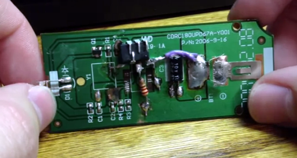
This project started as a simple microcontroller replacement on this IR camera remote control PCB. But the soldering job went rather badly for [Balthamos] so he changed things up and designed his own simple AVR remote shutter release and intervalometer.
The DIP chip seen with most of its legs bent backwards is the ATtiny25 which makes the system work. It’s patched into the traces for the battery connections, button (on the other side of the board) and the IR LED he’s pinching with his left hand. Point it at a Cannon camera and push the button to snap a photo. But as you can see in the clip after the break it also serves as an intervalometer; letting him take several pictures with a user-defined pause between each. That mode is selected by first pressing and holding the button. Once released the chip waits for a second button press to register the delay. The new circuit still fits in the original case after just a bit of alteration to it.


Anyone have any idea how much work would be involved in modifying this to work with Nikon (DSLRs)? I would imagine it would just be a matter of changing the LED blinking sequence, right?
Here are the timings for all cameras:
http://www.dslr-forum.de/showthread.php?t=435214
Awesome, thanks!
Cannon camera?!
Arrr… this be used to fire the cannon!
To shoot better photos.
And bigger, too.
It’s a camera of a greater caliber.