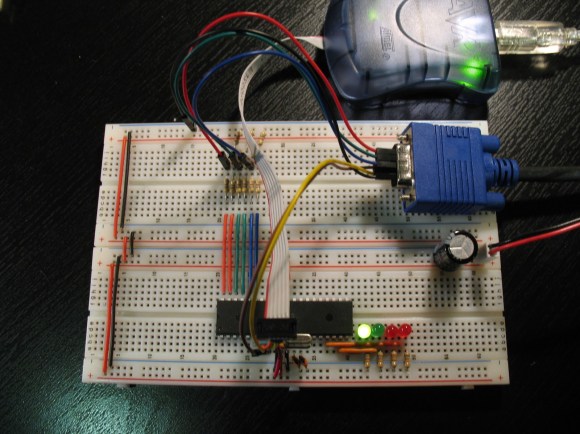
This simple circuitry makes up the hardware for [Andrew’s] AVR-based VGA generator. He managed to get an ATmega1284 to output a stable VGA signal. Anyone who’s looked into the VGA standard will know that this is quite an accomplishment. That’s because VGA is all about timing, and that presented him with a problem almost immediately.
The chip is meant to run at a top speed of 20 MHz. [Andrew] did manage to get code written that implemented the horizontal and vertical sync at this speed. But there weren’t enough clock cycles left to deal with frame buffering. His solution was to overclock the chip to 25 MHz. We assume he chose that because he had a crystal on hand, because we think it would have been easier to use a 25.174 MHz crystal which is one of the speeds listed in the specification.
Red, green, and blue each get their own two-bit range selected via a set of resistors for a total of 64 colors. As you can see in the video after the break, the 128×96 pixel video is up and running. [Andrew] plans to enlarge the scope of the project from here to make it more versatile than just showing standard images. The code (written in assembly) is available at his GitHub repository.


This is very awesome. I have to recommend a Propeller chip if you want to do vga out, but there is a lot of elegance in this method. I wonder if it’d play well with the 25.174?
Awesome but with the Pi doing HDMI out, it makes AVR chips like these look like dinosaurs.
The pi is enormous and very expensive compared to a single AVR.
Say you wanted to make a throwaway dongle to fit on the back of some monitors for a gag, you wouldn’t be using rpis for that would you?
RPi has major issues with overscan takes ages to get it setup right. Why is this? Howcome’s all my other HDMI devices work out the box? Just curious.
Because it is engineered for use with TVs, which by default (for some stupid reason) have some sort of 10% image zooming turned on.
Usually when you turn it off you get more visible picture from your other sources too!
Overscan from the analog era comes from many reasons. Early TVs used round surplus radar tubes, but the video standard still specified a rectangular image. In these TV sets the rectangular corners were just chopped off inside the tube resulting in a round picture hence the corners were overscanned.
In more modern sets with rectangular or semi rectangular tubes overscanning was still common. One of the biggest reasons being most consumer sets had shitty power supplies in them. The picture would bloom depending on the average brightness of the screen. If in one of these shitty sets you had it set with 0 underscan, then displayed a completely white screen the picture would shrink due to the power supply voltage sagging and then you would end up with black borders all around your image. This is why analog video had a program safe area. Basically content producers had to assume that about 10% of the image around the edges was unusable for display of things like text or graphical overlays. otherwise they would risk part of the text or overlay being cut off by the overscan. This program safe area still carries on in todays digital world. Some modern LCDs still overscan by a tiny amount usually less than 5%. Also commonly seen on broadcast TV networks, the logos will not be all the way over in the corner as you might expect. This is for people that may still be using old analog TVs with digital converters. These converters usually out of the box will only display the 4:3 center part of the 16:9 video. The logos are left pushed over a bit from the corners so they will still display on these old TVs that are cropping the 16:9 video.
Another reason for overscan once some information such as closed captioning was sent over “digitally” as patterns in the picture itself using line21 and other lower numbered lines, you needed the picture to be overscanned so you would not see these flickering patterns. If you have ever seen an analog tv with overscan turned off, one with a really bad power supply, or digitally captured analog video displayed on a modern tv with little or no overscan, that is what all those flickering white spots are at the top of the picture. Circuitry in the TV would detect and decode these patterns for things like closed captions, auto setting the time, and in some high end tvs actually being able to display the name of the currently airing program.
That’s not an issue with the Raspberry Pi. It’s an issue with Raspbian, the debian distro that the foundation provides.
Why not use an XMEGA ? They support up to 32 MHz natively (and require minimal adjustments when migrating from normal avrs )….
Why not use an x86 CPU?
Nice work, done alot of VGA work with FPGA’s luckily once you get it working on that you’re usually golden once you derive the proper clocks. Your milage may vary applies to digital tv’s more than ever. What works on one may not even on another of the same model!
I Did this for my school final… I ran into a bunch of problems. But I used a 16F877A chip running at 4 MHz and the only real output I got was a checker pattern. a basic off/on on the output… I tried to get it to run at 20 Mhz, but I just couldn’t get it to work.. Even though I failed the project, I got a 100% due to me recognizing the limitations of the chip in the writeup… The teacher was real impressed I was able to do as much as I did with it..
Well done :) Sounds like you have good (and enlightened) teachers.
Also of use for doing this, Quinn Dunki has done it with a Atmega324, running at 10 MHz instead of overclocking. Halving the resolution to let you get away with some better timing and a few other things like that.
An AVR project that isn’t arduino based? Have my eyes deceived me?
Yeah, that’s amazing. 15 years ago, 80% of Atmel AVR programmers were doing in C language, while the rest of the 20% (like me) were doing in Assembly language, the most beautiful and pure of all. With the flooding of Arduinos, now 95% of the actual “programmers” (if we could call them that) use this “dish washer yesterday, programmer today” kind of person to plug the “lego” style hardware and software. I wonder what is going to happen in 10 years to the microcontroller and hardware real knowledge. Recently in a neighborhood gathering, some wife was very happy about her husband became a computer programmer, well, as I am in the electronics and programming since the time of 4004/8008 chips from 1960, it was natural for me to approach the guy and start a conversation. After congratulate him for the new venue in his professional life, my first question was “how long are you in the computer programming?”, the answer was funny: “Since last weekend”… It came as a shock, but I continue with my questions: “What platform and programming language?”, of course the answer could only be “Arduino”…. well, yeah, that is a start.
Here’s another one: http://www.lucidscience.com/pro-vga%20video%20generator-1.aspx
There are plenty of other examples. One of the nicest is this demo by Linus Aknesson: http://www.linusakesson.net/scene/craft/
He is even abusing the SPI to output high resolution graphics.
Done it on an Uno once, used the timers for sync and SPI for pixel out, managed to get reasonably high res (2 actual pixels per soft pixel and 4 lines per soft line) that way
nice presentation, implementation props for sharing the code.
can’t wait to see the character se in action for updating images.t