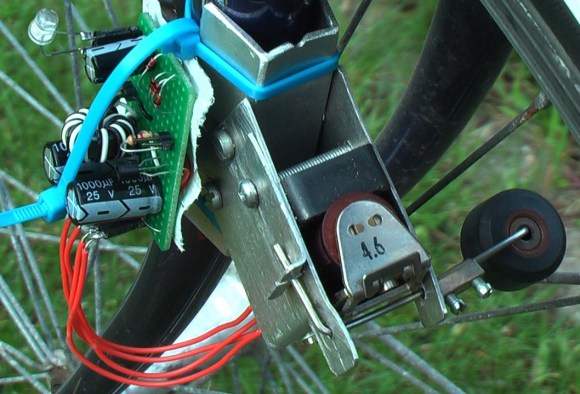
This project is in one of our favorite categories; the kind where asking “why?” is the wrong question. [Berto A.] built the device after observing some power generation by placing a large magnet next to a mechanical relay coil and quickly clicking the relay’s lever. From this humble beginning he built up the RattleGen, a bicycle spoke driven generator.
To get the most power possible he searched around for a massive relay and found one which was originally meant for telephone exchanges. He cut the case open and strapped a big bar magnet to the side of the coil. Next he fabricated an arm which will press against the relay’s lever. To that he added a small wheel which is pressed each time a spoke from the bicycle passes by it. This repeated clicking of the relay lever generates a current (and a rattling sound) that is harvested by the joule thief circuit built on some protoboard. An LED is illuminated, with excess current stored in the capacitor bank. Don’t miss the build and demonstration video after the break.


Interesting idea. I wonder how spacing some neodymium magnets around the rim, and a couple coils up near the seat would do. Kinda like those shaker flashlights.
Might as well just tape a few of those flashlights to the wheel along the spokes, they are pretty cheap. Plus it would be at least three times as loud
What? Why would it be three times as loud, when there’s no physical contact? The magnet is just passing the coil as the wheel rotates.
he is most likely thinking of the loud whirring of the plastic gears in crank flashlights, most likely not realizing its the gears making the noise and not the actual generator
I think he means attaching the whole shakeable flashlights on the spokes, perpendicular to the direction of the spokes.
@InsanumImgenium:
If the flashlights were placed “perpendicular to the direction of the spokes”, I could see
the magnet nesting in the rear of the flashlight due to centrifugal force and no longer generating current.
Wouldn’t the centripetal force keep the magnet along the outer rim, therefore generate no electricity?
Them flashlights would only work at low speeds, centrifugal (yep) force wouldnt allow them to shake, but just stay in their radial positions.
I think he is referring. To the shake light not the crank ones. My concern with this arrangements would be broken spokes or misaligned wheels.
When I read the title, I had visions of a bunch of shaker generators on the wheel, click-clacking away.
Yeah – I really wouldn’t want anything banging against my spokes – no matter how light the touch.
You never clothespinned playing cards to your bicycle forks as a child, for that “motorcycle” sound?
Paper is just guaranteed to not damage metal though
Sounds like you’ve never even thought of what BMX bikes go through. I’ve replaced four spokes and trued my wheel three times this month.
You could also turn this into a cool little analog speedometer. Measure the volt spikes before the smoothing, and then use the smoothed current generated to run a tiny microcontroller that calculates and displays the speed.
Microcontroller? THAT’s your idea of an analog speedometer??!!!
But really, this SHOULD put out a voltage that’s proportional to the speed, so you COULD make an analog spedometer by taking the DC output of your joule thief and running it through a resistor into a mechanical meter movement. Now THAT’s analog!
Neat though I always wonder why most bike generators (even this rattling kind) still insist on physical contact
Not all do: http://en.wikipedia.org/wiki/Hub_dynamo
neat though I was thinking more along the lines of having it in the rim (lined with NIB magnets)
You could charge the municipality a monthly fee for clearing all the nails and needles off the road, because those would be sticking to your wheel.
+1
Or the tire shops might pay you more not to clean flat tires of the street. :)
Something like Reelight? http://www.reelight.com/
You can get contactless magnet/coil based bicycle generators at most bicycle shops, they are just much more expensive than a contact-making type so they sell less.
I noticed a bridge rectifier was mentioned. Would it not be more efficient to use a pair of LEDs in a reverse bias setup?
LEDs are diodes with a higher voltage drop, so no. It would not be more efficient.
He meant “to make an AC LED, thereby skipping the voltage drop from the full-wave rectifier”
I personally wouldn’t trust it, though; the voltage range from the backdriven solenoid is so huge I personally would want much better regulation for anything more sophisticated than an incandescent light bulb.
As long as there’s a path for the current, there won’t be a huge voltage.
It would, but they would also be blinking and only when the wheel is really rotating. He stores the energy in a cap, hence DC.
Genius!
Its like a baseball card in the spokes that generates power. :D
The kid with the most spoke cards wins!
And playing cards are louder.
Pro-tip: double and triple up the cards for more sound.
Everyone seems to talk about using playing cards for this, but am I the only who cut peices from platic containers and used those. Much louder and longer lasting.
Remember to attach a piezo element to your cards, too!
Well, Baseball cards were also used…
I remember as a kid, people would advise against using spoke cards because it could weaken the spokes in the long run. If there’s any truth to that, wouldn’t this generator be just horrible?
The cards (and the thrill) wore out long before the spokes did.
But they where trying to scare the kids from making all that racket. Terrorist adults.
I had a bike generator that simply engaged a wheel against the edge of the tire. It was smooooooth. And it didn’t bang on the spokes. I suppose it could have picked up the energy from the edge of the rim, instead of wearing the tire. But regardless, it was continuous and far more efficient than this spoke smasher.
Aren’t there easier ways to destroy spokes, er, generate power without destroying spokes?
Well of course there are better ways, but I don’t think he started out looking for a way to generate electricity on with a bike. It seems like he was just tinkering with relays and had an idea, and is trying to take it as far as possible. I agree with everyone that it’ll never be clever, but it was an engaging idea for a few minutes. There was a time when the entirety of human knowledge about electricity was only suited (or at least, applied) for parlor tricks, but disinterested curiosity paid off in the end.
PS @Doing-o I don’t mean to sound harsh I just wanted to make that point. I definitely agree that a wheel-based generator would be better. Heck, while you’re at it, have an Arduino vary its radius from the axle and make it a generator with a CVT.
I’ve thought of using an extra idler sprocket (such as found with derailleur shifting) attached to a generator, but of course, it wouldn’t generate power while coasting.
Aha! At times people have tried putting the freewheel mechanism on the crank instead of the wheel so the rider could shift with derailleur gears while coasting. This would also allow for your idler-type generator to work while coasting.
The great thing about this hack is he’ll need to invent something to automatically true his wheels in the very near future!
The important part of the rattlegen is the fact that only a quick pressure on the contact lever makes a usefull amount of energy. The gap is 1 mm/ 0,04inch. What happens if this is more? What by changing the position of the magnet? The static relay magnet setup makes this generator nearly solid state and durable. Everything needs to be optimized. The noice can be avoided by the use of ‘contactless’ small magnets on the wheel rim pulling the contact lever.
Or, if you like this kind of things, there is an other electro-magnetics trick with http://www.kickstarter.com/projects/dynamodirk/magnic-light-get-new-energy
I think that both the rattle generator and the “Magnic Light” can “simply” be explained with electro-magnetic theory (i.e. Maxwell equations) but I forgot how to use them for a few years already.
If someone comes up with an explanation of why and how these two things work, it would be if great interest.
The magnic light page explains it, as a user on this page already has. Basically a static magnet induces electricity (eddy currents) in metal that’s moving past it (the relay lever. Or a bike spoke. Or an electric guitar string). The metal doesn’t have to be magnetic, just conductive.
This current produces it’s own magnetic field, which is also moving along with the relay lever / bike spoke / guitar string. This moving magnetic field induces electricity in the static relay coil / Magnic Light’s coil / guitar pickup coils.
And that’s where the power comes from, and also how electric guitars work!
A bit crap really for efficiency. In this project’s case it’s possible the moving spokes are inducing more of the current than the little relay lever is. Berto could try removing the actuator that moves the lever, no moving parts other than the bike’s wheel. If it still worked, we’d see.
It’s still just taking energy from the motion of a magnetic field, just an eddy-current induced one. The advantage the Magnic Light has over a dynamo is that nothing touches the bike’s wheel, so no friction or wear. The down side is the efficiency, but that’s enough for the Magnic. Think Berto’s project could be more efficient if he used the same method and optimised the positions of the various bits.
Thanks for this very usefull comment.
Welcome, dude! I always like to see what you’ve been up to since the last time HAD
mentioned you. You’re a true experimenter.
I’m actually curious how efficient this method can be. Either on a bike, or perhaps you could make up a rig with various options instead of a bike wheel. I suppose driving a wheel with an electric motor, measuring the power going in, then measuring the power coming out of your generator, would give a useful approximation.
This is what I believe is happening. The magnet on the coil bobbin creates a magnetic field around the coil. The movement of the relay armature produces a change in that magnetic field simulating movement between the magnetic field and the wire in the relay coil inducing current flow in the coil. No ground breaking electrical discovery, but a novel way to create movement between a magnetic field an a wire.
Gut a cheap LED flashlight and as some wire and you have a new headlight.
Get a cheap LED flashlight, period.
Mine typically lasts about 6 months (intermittent use) on 3 NiMH AA batteries.
Somebody has to say it -dung, no matter how delightfully cooked and presented, is still dung.
It’s, erm, an “interesting” invention! I’m sure we all know, and Berto knows, that if you wanted efficiency a normal dynamo would be much better. But this is a curious generator. I don’t understand what the lever’s actually doing. Is it simply that it’s made of iron, and is therefore moving the magnetic field a tiny bit?
Berto’s well-known here for fitting crazy things to bikes, just out of curiosity. I remember his boat-bike from the last time.
You would think that someone, somewhere, has made a regenerative braking widget for a bicycle. that would be a great project, BTW.
Say your bike weighs 10 kilograms. You weigh 60. You’re traveling at 20mph (32.1km/h). Your kinetic energy is thus 2797.83J. Let’s say you need a stopping time of 4 seconds. That means you need to dissipate energy at a rate just under 700 watts. Let’s say your generator is 20% efficient. You thus are generating electric energy at a rate of 139.9 watts. Let’s say your generator outputs 12V, this means you need wiring enough to handle 11.65Amps. This is thick. Also the generator’s internal wiring needs to be thick enough to support this. This energy needs to go somewhere too. LiPo batteries should be charged at no more than 1C (more is possible, but degrades their life and heats them), so if you want to dump that energy into a LiPo, you’ll need at least a 139.9Wh battery. This is huge and nontrivial.
Your options are a huge battery pack and a huge generator and thick wires.
Alternatively, you can go for high voltage. Using a generator outputting 60V, you only need wires thick enough to handle 2.33Amps. Definitely more reasonable. But, battery size does not change, actually, except from a pack with 3S config you go to a pack with 14S, making balancing hell.
To summarize: not a trivial problem, IMHO
Supercap?
They do not store much energy per weight, AND are voltage limited at 2.5V, so you’ll need a large string in series.
Do they need to? Apparently that’s how (at least some!) electric cars work. You can get electric-car-type supercaps on surplus, 2.5v as you said. They can take a very high charge current. Plus you could run the generator at 2v, or at least through a transformer down to 2v, although it’d need to be big, to avoid it saturating. Or, you could use a chopper to bring the frequency way up to use a smaller transformer. Or, finally, have the generator itself run at a high frequency, through using more coils, and also a bit of gearing.
It’s a pain cos when you put capacitors in series, you lose a lot of the capacitance. Not sure why, but I know the equation. So you’d be best operating at the cap’s own voltage. Tho that depends how much capacitance you actually *need*, don’t suppose you fancy doing the maths? You can get caps with 2600F (yeah really, Farads) at 2.5v.
Somewhere there’s a combination of stuff that can do it. It works in electric cars so a bicycle should be possible, taking up less space than you’d get in one of those cargo boxes that mount by the saddle.
Just to point out, irrelevantly, how in awe I was when I first saw 1 Farad supercaps, at 5.5v, back in a catalogue for the first time! About 20 years ago. Amazing how far things can come, eh? Blue LEDs cost a few pounds each, red and green were about 15 pence. There weren’t any white. Though some wise men had ideas about how to get white light…
At least in chemistry, and stuff at the small end. Shame spaceflight hasn’t gone the same way. Or those cars that drive you across the world at a million miles a second and run on a drop of petrol.
And now I can get cigarette lighters, 4 for a pound, with white LED flashlights built into the bottom! With 2 batteries included! And it lights cigarettes as well.
Not to be too picky, but…
1) It would not be sized for 20MPH to 0MPH. Think more like 20-5MPH, with 5-0MPH being done by normal brakes.
2) Couldn’t any extra power produced in a sudden event be dumped as heat, via a power resistor? I know this is a bit of a bad example, but KERS in F1 cars does this already. The reason for that is to not upset braking balance during the lap. We are talking about a lot more power.
3) Do we need a DC motor, or can we use a poly phase one? That would lower the amperage required by each winding. The other advantage is if we make this a 3 phase 120 degree alternator, is that AC to DC conversion is easy to do on 3 phase systems. This would allow using capacitors to store the extra power to more slowly charge the the LiPo batteries with later.
I agree about the voltages needed from the “generator”, but it’s easy and trivial to do voltage conversions on AC power, less than ideal efficiencies in something that would fit on a bike, but easy to do as a prototype.
I wonder if there is a way to use a DC brush-less motor for this. As speed controller are readily available, and I’m not sure that there speed controllers available at the hobby level for 3 phase AC motors (Yes VFDs exist, but I know they are not cheep, or really available in the sizes we are talking about here.)
Dumping the extra power as heat is exactly what modern trains do, which is why you see big fans on top of the locomotive. The diesel engines actually power electric motors, the motors switch operation to be generators to create braking force by pumping the generated current through coils. The heat is pumped out the top of the engine.
You have to wonder how much they could save by fitting some batteries or capacitors to store that power somewhere. Depending on the rolling resistance of a train, how much energy is needed to keep them going over friction, air resistance etc, you might be able to cut the power use down a lot.
What about electric trains? Do they send the power back down the third rail / overhead line? I think it’d mess up the voltage stability of the power supply, but does that really matter when it’s just driving enormous great train motors?
First, “hybrid” locomotives are being tested and we might see some in use in the future, but the energy in a moving train is huge, so the batteries just to help pull it up the next hill will have to have huge capacities. Second, yes, at least some electric trains push power back into the supply grid when they use “dynamic braking”.
I think what’s missing here is that saving the energy from a bicycle stop isn’t very important. What would really help is to capture the energy from continuously braking a bicycle going down a long hill. The instantaneous power won’t be as much so will be easier to deal with, and the total energy available for capture will be much more, unless you’re riding around Florida or Louisiana (in which case regenerative braking isn’t really very helpful).
Electricity? Pfft. I always wanted to make a bike regen with an air motor and tank. Much lighter and no pesky battery limitations, and likely more efficient. By the way 12 amps does not require a massive wire – at a low duty cycle like this #18 should do fine.
Where’d you get that? A pneumatic drill or power tool or something? Or can you buy compressed-air motors? With the right size, capacity etc? And then just use a normal tank that a compressor would use?
Hmm, if you gave it assistance, and coasted, it might have time to fill the tank between boosts, and you’d be able to cycle on quite a low-powered motor. I wonder about those tyre-inflating pumps you get that run off the cigar lighter. They must put out some pressure to be able to take 1/4 the weight of a car pushing back.
I’d actually love to see that! For regenerative braking, connect the pipe to the motor’s backward-driving port (assuming it has one), then through a one-way valve, so it opens when the motor’s creating more pressure than’s in the tank. Should do it, right? You’ve always wanted to! You know you should do it! Then post pics!
Hey, you could even fill it up with air at the garage!
Aren’t we supposed to be the engineers who say “yes” instead of “no”?
It seems like there is not anything close to a show-stopper here. Electric-assist bicycles are a big deal in China, and there are some US high-end models as well (see PiCycle). Plus the NZ-based YikeBike, which I think is crazy and awesome. Those already have batteries. It shouldn’t be a problem to deal with the overcurrent issue through a little bit of clever engineering.
I always love how people start with rough estimates for the initial parameters, and then use an abundance of significant digits in the rest of the calculations.
Actually FWIW, electric motors are something like 90% efficient at turning electricity into movement. I’d assume generators are the same. So if they are, quadruple your figures.
what about using a super capacitor for picking up and storing the regen’s power? It would eliminate the problems associated with the rapid charging of the lipos, would it not?
I’ve been toying with the idea of an e-bike build and I would like to incorporate regen technology into the build.
I saw a version of this using bungee cords as a college project.
He could call it a Wankel generator
I don’t see how it works as described.
” By pressing the contact lever I changed the magnetic flux inside the core of the relay”
Merely shorting and unshorting the coil will not change the magnetic properties of the relay while it’s in a steady state. It must be the motion of what I assume is a steel lever that changes the field, and not the switching of the coil itself. Disconnecting the coil while simultaneously causing a sharp change in the magnetic flux does induce a rather large voltage, because it’s not the strenght of the field that makes the voltage but the rate of change.
You need more field strenght if you want to induce large currents as well though, because of the back-EMF from the coil.
it uses the same principals as a boost converter, the difference here is the field moving over the coil is moved physically (by moving the magnet) instead of generated electronically by transistors switching states. =)
I don’t think the magnet moves. Took me a while to figure out since the relays he uses aren’t like those I usually see, but as far as I can tell it works similar to this contraption:
http://www.youtube.com/watch?v=HI5ERdvroec
The relay he uses happens to have the armature that when closed makes a circuit which goes through the core of the solenoid (as far as I can tell). It seems this rattlegen could be made without the rattle by using a rotating assembly which allows the magnetic flux to flow and not flow.
It could be done by just allowing the spokes of the wheel to pass sufficiently close to the coil.
Maybe I’m missing something here, but what’s the point of having a magnet taped to the relay?
To act as a source of the magnetic field.
It’s a kind of a switched reluctance generator where moving a piece of metal causes the magnetic path through the coil to change, and that causes a shift in the field which induces a voltage.
If you take a permanent magnet, wind a coil around it, and then introduce an iron nail to one end of the magnet, then remove the nail quickly, that will cause a voltage spike in the coil.
I see! So in that case, I guess the arm that clicks the relay is just providing rectification.
It occurred to me that a hard drive head-arm-magnet assembly could be used as a near linear generator. Knee or hip-ster cargo pants with joint flexing recovery. Or pendulum hanging to capture any waste motion.
I have a full suspension bike I like to recover that waste energy silently.
Haha, love it!
Coolest bike light:
http://www.kickstarter.com/projects/dynamodirk/magnic-light-get-new-energy
and the working principle:
http://patentscope.wipo.int/search/en/WO2013004320
It’s sort of funny that he thinks he invented this.
I actually expect it’s one of the oldest setups ever and I expect the people laying the foundation of the theories on electricity must even have made similar things.