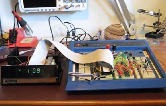
One of [Bob’s] most treasured possessions is a Heathkit alarm clock he put together as a kid. Over the years he’s noticed a few problems with his clock. There isn’t a battery backup, so it resets when the power goes out. Setting the time and alarm is also a forward only affair – so stepping the clock back an hour for daylight savings time means holding down the buttons while the clock scrolls through 23 hours. [Bob] decided to modify his clock with a few modern parts. While the easiest method may have been to gut the clock, that wouldn’t preserve all those classic Heathkit parts. What [Bob] did in essence is to add a PIC32 co-processor to the system.
Like many clocks in the 70’s and 80’s, the Heathkit alarm clock was based upon the National Semiconductor MM5316 Digital Alarm Clock chip. The MM5316 operates at 8 – 22 volts, so it couldn’t directly interface with the 3.3V (5V tolerant) PIC32 I/O pins. On PIC’s the input side, [Bob] used a couple of analog multiplexer chips. The PIC can scan the individual elements of the clock’s display. On the PIC’s output side, he used a couple of analog switches to control the ‘Fast’, ‘Slow’, and ‘Display Alarm/Time’ buttons.
The PIC can now read and change the clock’s time and alarm. By pressing all three buttons together, it can reset to a known state of Midnight. The only thing missing was a real time data source. [Bob] added a GPS to the system to accomplish this. The GPS receives the current GMT time from satellites and sends that data to the PIC. The PIC then offsets this by a timezone value stored in NVRAM. Alarm time is also stored in NVRAM.
At power up the PIC first sets the clock’s alarm. Then it waits for the GPS to sync. Once it has GPS time, the PIC sets the clock. The PIC also resets the clock time every night at midnight. The MM5316 is still in control of keeping time hour to hour. This is a great hack, and a really nice way of adding functionality to a classic clock with a beautiful VFD display.


Nice and reversible hack! And bonus points for using a Heathkit breadboard to develop the circuit on is a nice touch.
Heatkit Clock should be Heathkit Clock (In Title)
Second
Do they ever fix typos? I don’t know if I’ve ever seen it happen.
They fixed the typo!
Sorry about that. Just my luck, I misspell Heathkit once, and it’s in the title! One of the other editors actually got to it first. I was dealing with a clogged sewer line at the house (yuck).
Praise the sun!
I think they had an ulterior motive in this case. It was in the title, so fixing it was important to SEO.
(That’s Search Engine Optimization. I don’t want to start another acronym flame war.)
>I think they had an ulterior motive in this case. It was in the title, so fixing it was important to SEO.
Except they didn’t fix the URL, just the title.
They really ought to fix the title, then use .htaccess or something to point the old title to the new story link with a “301 Moved permanently” or something.
Quote: “VFD display”
Why does hackaday always assume that every visitor knows / remembers every aspect of every technology.
As I remember there two types of display like this from that era, one (as shown) just used the neon effect with different gasses for different colours, the other use phosphor so that it could have different colours.
Even so I have no clue what VFD is and I am not going to goole it so in effect it just reduces the quality of this article for me.
Why didn’t you include PIC32, NVRAM and GPS? Because, after all, we can’t know what everything is without having it explained to us in detail, right?
PIC32 is not an acronym and it is described as a “co-processor” although it’s actually a micro-controller.
Non Volatile Random Access Memory contains “RAM” which most people can generally understand as they’re familiar with from computer RAM.
Geo Positioning System is common now, most phones have it.
The above is just my opinion from what I know so your comments are equally valid.
PIC32: (32-bit) Programmable Integrated Circuit; a microcontroller which is being *correctly* described as a “co-processor”.
GPS: *Global* Positioning System
A co-processor performs functions under the direct command of the main processor and returns the results of such functions. As the PIC is not directly commanded by the clock it cannot be considered a co-processor. If anything the clock is being commanded by the PIC. However I doubt you would call the clock a co-processor as it forms the function of an interface and with it’s very low gate count it doesn’t really reach the definition of a processor.
A micro-processor and (co-processor) have the ability to perform computation function but have no ability to interface built in. On the other hand a micro-controller has both the ability to perform computational function and has the extra ability to interface built in. So a PIC can’t be considered a co-processor as there is no external direct connection to the actual processor.
PIC by itself stands for Peripheral Interface Controller and not Programmable Integrated Circuit. What is printed here is PIC32 and is therefore not an acronym. The PIC acronym is later used but only as a specific reference to PIC32.
If you’re over 20 (in the US at least), you’ve seen a VFD. They were in every VCR (remember those?), early DVD players, and apparently clocks. In fact, I think they’re still in use today in DVD/Blu-Ray players, and some test equipment (though I might be wrong).
I think it’s a given that the vast majority of HaD readers are over 16, and therefore most people will know what a VFD is, and what it looks like. The fact that you’re too lazy to go to wikipedia is your fault. HaD writers do not have to pander to your ignorance.
Besides, if you so much as opened the wikipedia page on Vacuum Fluorescent Display you’d instantly recognize it, because you’ve seen them everywhere.
Guess what, over 20 years ago I owned and worked at an electronics repair centre and I fixed a lot lot lot of (some times 15 a day) Video Cassette Recorders that had both of the types of display that I mentioned earlier. They were never called VFD’s.
It’s interesting the you chose the word “ignorance” when you could have used the term “lack of knowledge” (or many other terms) so I ask what do SML, SNRZ, GV all relate to as I certainly know.
Do you have the answer or are you eh em … ignorant?
Typo, should have been “SLM, SNRZ, GV”
What? 20 years ago I worked at a TV/VCR/Stereo repair shop, and everyone called vacuum fluorescent displays “VFD”s, because that is what they ARE!
I seem to remember the user manuals referring to them as displays or data displays and the service manuals referring to them as displays or fluorescent displays. It was kinda assumed that if you’re a technician then you kinda know that it has a vacuum inside.
But hey, that’s just my memory and time erodes memory.
So here’s the deal, I concede that I’m wrong and you’re right.
You’re a true God of technology.
So kindly impart some of your vast knowledge upon us and tell us what SLM, SNRZ and GV all relate to.
And if you can’t then is it because you are “ignorant” as rexxar would have us believe.
Or just maybe (as was my original point) HAD shouldn’t assume that all readers remember all acronyms from all of time. Faaaark, hand me the keys to the TARDIS.
Also it’s (edit: it was) a convention in English to use the full name of an acronym on the fist use with the first letters capitalised and thereafter use acronym itself.
But yeah, that was from a time when we knew the difference between you’re and your, their, there and they’re.
Great attitude you’ve got there.
“I’m too lazy to Google as common term”
“Despite being in the industry, I don’t never learnt nuffin'”
“Yeah well, I smart ’cause I made up some acronyms that you don’t know!”
“I’m a grammar Nazi too” (When all else fails, try that)
Your only valid point is that HAD should spell out abbreviations the first time they’re used, as is proper writing practice. However, HAD editors are well-known (perhaps not to you though) as being rubbish, eg the mistake in the title, so that won’t happen.
We’re just grateful they know what a paragraph is.
As pointed out VFD is a very well known term, as are LCD & LED – if you don’t know what the letters mean it doesn’t matter, you know the type of display. Even advertising material will state a display is VFD, ’cause VFDs are cool.
(A VFD is also a motor controller – somewhat less known.)
Your argument that RAM & GPS don’t require spelling out as they’re ‘well known’ is rubbish. They should be spelled out, however you cater to your audience and assume they’ll know these terms, and if not they can Google it; which is actually faster than writing a post whining about how you don’t want to.
Anyway, given HAD called it a ‘VFD display’, I’m not sure them stating ‘Vacuum Fluorescent Device Display’ would have helped you all that much as you didn’t know what that was either.
Unlike VFDs, you don’t seem to be too bright.
Merriam Webster says: Ignorance (n) a lack of knowledge, understanding, or education : the state of being ignorant
*ahem*
I don’t know what any of those acronyms are, so yes, I’m ignorant of them.
There’s not knowing about a subject, and then there’s being willfully ignorant by not even doing a cursory search. Frankly, you don’t have the right to complain about HaD writers using the term VFD if you’re too lazy to look it up.
Do you know what I do when I come across something I don’t know about? I look it up. I pull up the wikipedia page, and if I don’t quite understand, I’ll ask in a forum, because there are plenty of old hats out there who act like adults and want to further knowledge.
I’m in my late 40’s and this particular type of gas discharge display has been called a vacuum fluorescent display as long as I can remember. Just for kicks I pulled my TI Linear & Interface Circuits Applications, (C) 1986 and in Section 8, “Display Drivers”, on page 8-29 the introduction to subsection “Vacuum Fluorescent Displays” begins with “A vacuum fluorescent display (VFD) operates…” along with a diagram of a display just like that used in the Heathkit clock.
A neon is a gas discharge display. It relies on the photonic emission that occurs when an electron that has been accelerated to higher orbit by a potential difference then returns to it’s normal orbit. Vacuum Fluorescent Displays are not Gas Discharge Displays. They use the potential difference to heat the phosphor which then in turn emits the light as a result of the heat and NOT the potential difference. i.e. it is NOT the gas that is discharging.
Good to see you’ve found Wikipedia. Google is great, ain’t it?
You’ve STILL got it wrong! And I’m amazed you’ve only just heard of VFDs, they’ve been in, like, everything, forever.
It’s not the phosphor that’s heated. I can’t think of anything that glows when heated, except with black-body radiation.
In a VFD the cathode is heated, which causes it to emit electrons, just like in a thermionic valve / tube. These electrons are controlled by a grid, and if they hit the phosphor, it glows. So it’s half thermionic valve, half CRT.
this Rob bloke should keep his nose out of stuff in the future to avoid further embarrassment.
The need to have electrons flying around is why it needs a vacuum. The “vacuum” part is also what makes it obvious that it doesn’t use gas-discharge. “no gas” is sortof part of the name.
Why not google it? It would be about 3 seconds before you think “Oh, that thing”
VFDs are Vacuum Fluorescent Displays. They are essentially vacuum tubes, but with a phosphor on the plate so it glows when powered. They take 40-90v to power, which is less than normal fluorescents (in the hundreds of volts) but still far more than LEDs. (Light Emitting Diodes)
I’ve got a few nice very small ones that light reasonably at 5V, and look great at 12V. They were new old stock from a bunch of cheap car radios, so I assume they ran at car battery voltage.
Ones I’ve pulled out of VCRs and DVD players run at closer to 30V.
You think looking at the picture would give you a hint, but Rob seems to be a bit dim.
Most modern VFDs are low voltage. You actually need two voltages, a low (say 3v) for the filament, and maybe 12v for the rest.
They’re also generally meant for AC, not DC, which can be a bit of a nuisance. On DC the display will be bright on one side and get fainter going across. Small displays are ok, or you can up the volts or fake AC by switching polarity.
You want the AC only on the filament.
Hi, Martin. I dunno about the “conductive film” (maybe if I opened the display and measured the back of the glass with an ohmmeter? Nah, then I wouldn’t have the clock any more!) ;-P
The glass being [i]behind[/i] the cathodes, I can’t imagine how it’s working; I think it might be an electrode on the substrate behind the digits, turning all segments partially “on”. This is speculation — there was an old trick with LED’s biasing them partly on (very dim), to reduce the drive current, drivers then turning selected segments more “on”. Being a vacuum tube, the anodes (segments) attract electrons boiled off of the cathode. The higher the anode voltage, the more energetically it sucks up the electrons. (Sound of a slurping straw….)
RE “running the filament with AC” — the filament doesn’t care what energizes it, often it’s driven directly by a low voltage transformer winding; of course the digits are DC, a common DC ground (to the clock circuit) is tied to the hot filament. So the filament is DRIVEN by AC, but electronically the vacuum-tube display works off of DC…
PS — sadly, the VFD timer/clock is now mine. I posted here in March 2015; brother discovered “adenocarcinoma” in June, and lost the fight November 13th.
<:'-(
The VFD (Vacuum Fluorescent Display) uses the phosphor which fluoresces under electron bombardment in vacuum. Hence the name. It does not use gases like neon. If you do not know it and do not want to google it, it’s your own fault.
>The PIC also resets the clock time every night at midnight.
Wouldn’t 2 AM be a better choice? I mean, that’s when we “fall back” or “spring forward.”
Oh and any clock that relies on counting 60 hz power cycles will stay accurate to the second as long as the power is on. That means my clock radio from 1982 is more accurate than the clock they built into my motherboard (c. 2012), discounting regular corrections via NPT.
http://www.techlib.com/electronics/atomic2.html – 1 IC atomic frequency standard
http://en.wikipedia.org/wiki/Hammond_Clock_Company
And hopefully WWVB will be worth a damn on the east coast soon – http://xtendwave.com/atomictimekeeping.html
The mains frequency varies throughout the day, depending on load, so clocks will not be accurate to the second. Here’s an interesting graph showing cumulative error (this is in Europe, but should be similar elsewhere) http://wwwhome.ewi.utwente.nl/~ptdeboer/misc/mains.html
>The mains frequency varies throughout the day, depending on load, so clocks will not be accurate to the second.
Obviously, the engineer in charge of power in the Netherlands never got a free clock from the Hammond company. While the 80s clock radio only shows minutes, it has remained accurate for month within the a few seconds. I cannot say the same thing for my PC without regular NTP corrections. Yes, I understand frequency can change throughout the day, but they seem to take special care to keep the total number of cycles consistent. BTW, I have a kill-a-watt and the voltage peak-to-peak changes quite a bit compared to the frequency. I can set it up and watch the power brown out in the early afternoon during the hot and humid summer when everyone wants their AC to be on full.
@Standard Mischief: the clock chip has a feature that allows you to reset the time to 12:00:00, so I do that at midnight. It’s the easiest way to reset the seconds. Obviously, 2 AM wouldn’t do the trick.
@Bob
As I said elsewhere, the AC line frequency in my area is so tight, and my clock-radio variance tolerance is so loose that there’s really no need to correct it for time drift.
When I really need automatic clock adjustment is two instances, 1) power restored after outage, and 2) $#!++y a$$ daylight saving time. Any computerized solution to setting and resetting and resetting clocks for me needs to handle these two instances.
If anyone needs an example of inefficiency in government, I present WWVB. While it would be dirt cheap and super simple, you just can’t reliably get WWVB on the east coast (Major USA population area) on anything smaller than a breadbox. Double frustrating as WWVB originally use to transmit from just outside of DC back in the tube era.
They’ve got a new promising format for WWVB, so maybe things will finally work well enough that I’ll never have to set another clock in my life ever again. Now if they could only get me my flying car.
GPS still has some issues indoors, but it works most of the time and prices are falling fast.
Microcontrollers are cheap and easy to program nowadays. I can’t really understand why if it can be programmed to reset the time after a power outage, it can’t be programmed to look for the DST flag from WWVB or GPS, wait until 2 AM, and then press three buttons, and then hold down the fast forward to correctly gain or lose and hour.
Something else funny. My Palm from 2004 was smart enough to advance and retard the clock on the proper hour and day for DST, but my TomTom from 2009 wasn’t smart enough to do likewise, despite the fact that it listens to orbiting atomic clocks and therefore knows what time it is and which timezone I’m currently in.
Standard Mischief, if I set the clock at 2 AM, I need to “push” the three buttons, then fast forward. At that hour, probably no one’s watching, but if they are it’ll look weird. In contrast, if I reset at midnight, I push the buttons and I’m done. And no one will notice a thing. I don’t see any benefit to doing a more complicated operation at 2 AM.
GPS doesn’t have a DST flag. It’s unfortunate but understandable given that GPS is global, not U.S.-only. I thought about programming in the DST rules, but they can change on Congress’ whim. At least setting DST is a lot easier now.
My main motivation for resetting at midnight was not drift in the AC mains. Instead, it was the unpredictability of the seconds when the clock first gets power. Resetting every day instead of only at power-on took less code while ensuring that drift in the mains never became a problem.
I agree with you about WWVB. I tried using it initially and gave up (I’m on the east coast).
Since many have a Heathkit GC-1005 that uses a Mostek MK5017AA or MK5017AN that are unavailable, how can these clocks be modified with a PIC to make the clock operable again? thanks.
First step would be getting the complete datasheet for the MK5017. I was only able to find the first two pages at http://www.decodesystems.com/mk5017.html. The pinout would be incompatible with any microcontroller, so you would need a board that holds the PIC and any additional circuits it needs, and that plugs into the MK5017’s socket. It’s certainly do-able, but I doubt anyone has done it yet.
Are you sure the MK5017 is the part that failed? It’s not unheard of for an IC to fail, but I would suspect other components first.
I had made a clock in the early 80’s based on a 5316, but with a liquid crystal display — lit by a green neon. The neon burned out long ago, and brother’s eyes had diminished so he could no longer see it. Saw a clock on ebay from China based on a PIC, but had a NON-MULTIPLEXED vfd. (3.5 digits + am/pm, 35-ish pins, no grids!) Perfect for the 5316. Never seen that display before or since! Pulled it from the 12V Chinese board, hooked it up to the 5316, but it was very dim. Started playing with the “unused pins”, hooked up a left-unused-pin to +12 and the left side lit up brightly! Hooked up a RIGHT-unused, and the rest of the display lit up brightly! Clock works fine on 12v (big power resistor to ballast the filaments), doubles as a NIGHTLIGHT. I’d love for someone to tell me how those two +12V pins affect the display! < :-/
Seems, that this pins work slightly similar to grids (one for the left half and one for the right half), perhaps for 1/2 muxing, what is sometimes done with the mains AC by driving the left and right halfes with opposing half wave rectifiers. Are this unused pins connected to some transparent conductive film on the glass, acting as acceleration electrodes?
Sorry, I clicked the link from my “email notification” — it posted above on Rob’s discussion. :-o
The timer/clock works very well with the Chinese display (okay, I’m certain it’s Japanese, probably Futaba — Nick Price said he’s most usually the designer for every VCR and microwave display! Very nice guy — he was behind the “analog VFD clock display” being sold on ebay, fun clock with 60 two-segment hands.)
Yes I have a tiny PIC-based alarm clock from Kosbo in England (sparkletube), it lights the appropriate HANDS to show time. Multiplexed in twelve grid fields. Turquoise like most all VFD’s, can be filtered to any color (including white!)…
I tied the two outputs of the 5316 on the timer/clock into 120v triacs, via MOC3010 isolators. Brother wanted the clock to turn on the radio & cassette deck and record timed programs, it did that very well. I’ve considered activating the “common source” pin on the 5316 — as bright as the display is, it will live longer if it’s a bit dimmer. (Though the way the world is going I’m not sure any of us will care about our clocks in a year or two…)
8-/
Hello,
I saw a post of yours about a Heathkit GC1107 clock. I built mine in 1980 and it worked flawlessly until about a month ago, when it became stuck on the time 0032 (I built it in 24 hour mode). Flipping the various switches or trying to set the clock with the switches did nothing to change the displayed time.
I ordered a NTE2061 chip to replace IC-1. However, when I powered up the clock a segment on the display didn’t light up and the clock did not advance time. Luckily I got the chip from Amazon and they refunded my money.
Do you have any suggestions on how to fix this clock?
Thanks so much for your help!
Dan Calzaretta
I think the first thing to do is to check all the inputs to the clock chip and see if they’re working. The low voltage 60Hz clock signal is the first thing to suspect. If it weren’t working, the clock would not advance (e.g. be stuck at 0032). It’s also possible that the clock chip won’t respond to the switches without that 60Hz clock.
BTW, you’re lucky I’m still subscribed to this HaD post. A more reliable way to contact me, however, would be to go to my web site (this HaD post has a link to it at the top) and use the Contact link. Contacting me directly is better than posting in a third-party forum and hoping I see it.
– Bob