Arduino Keypad Door Automation

arduino door pad

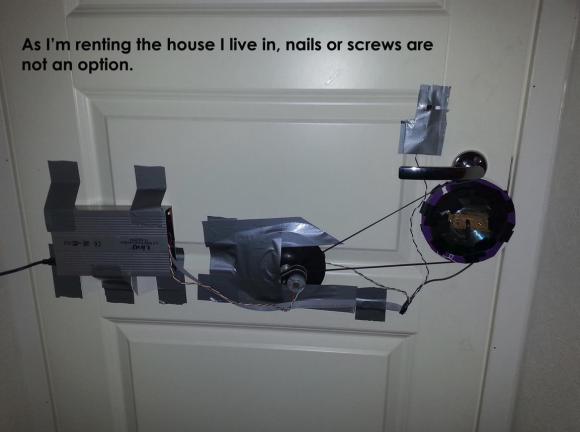
[Andrea] just sent us this great student hack he made for his room. He’s constructed an Arduino keypad door lock — without using any proper fastening hardware!

The entire build is made out of scrap parts he had lying around: some DVD’s, a bit of wood, an allen key, a motor and belt from a broken printer, an old hard drive enclosure, and a few power supplies. As you can see the entire setup is held up rather artistically using good old duct tape.

The system auto-locks after 5 seconds, and just in case, [Andrea] has hard-coded in a few safety codes into the firmware to allow him to forcefully open the door — you know, if it malfunctions or something. Not overly confident in his code, he also has it reset every 5 minutes of idling to safeguard against potential memory leaks — probably a good idea! All in all it’s a very cool build, and we have to give him props for not damaging the door to mount it! Down the road he’s also planning on adding a knock sensor using the small speaker that is already part of the circuit, because, why not?

Stick around after the break to see this magnificent contraption that would make Red Green proud.

Continue reading “Arduino Keypad Door Automation”

Deconstructing Apollo Flight Hardware

[Fran] has been researching the Saturn V Launch Vehicle Digital Computer – the computer that flew all the Apollo flights into orbit and onwards towards the moon – for a while now. Even though she’s prodded parts of the LVDC with x-rays and multimeters, this is the first time she’s committed to a little destructive testing.

After [Fran] took a flight-ready LVDC spare to the dentist’s office for x-raying and did an amazing amount of research on this artifact from the digital past, there was only so much she could learn without prying apart a few of these small, strange chip packages. Not wanting to destroy her vintage LVDC board, she somehow found another LVDC board for destructive reverse engineering.

This new circuit board was a bit different from the piece in her collection. Instead of the chip leads being soldered, these were welded on, much to the chagrin of [Fran] and her desoldering attempts. After removing one of these chips from the board, she discovered they were potted making any visual inspection a little difficult.

While [Fran]’s attempts at reverse engineering the computer for a Saturn V were a bit unsuccessful, we’ve got to hand it to her for getting this far; it’s very, very likely the tech behind the LVDC was descended from ICBMs and would thus be classified. Documenting the other computer used in every Apollo launch is an impressive feat on its own, and reverse engineering it from actual hardware, well, we can’t think of anything cooler.

Heathkit Clock Updated With A PIC32 And GPS

heathkit-clock

One of [Bob’s] most treasured possessions is a Heathkit alarm clock he put together as a kid. Over the years he’s noticed a few problems with his clock. There isn’t a battery backup, so it resets when the power goes out. Setting the time and alarm is also a forward only affair – so stepping the clock back an hour for daylight savings time means holding down the buttons while the clock scrolls through 23 hours. [Bob] decided to modify his clock with a few modern parts. While the easiest method may have been to gut the clock, that wouldn’t preserve all those classic Heathkit parts. What [Bob] did in essence is to add a PIC32 co-processor to the system.

Like many clocks in the 70’s and 80’s, the Heathkit alarm clock was based upon the National Semiconductor MM5316 Digital Alarm Clock chip. The MM5316 operates at 8 – 22 volts, so it couldn’t directly interface with the 3.3V (5V tolerant)  PIC32 I/O pins. On PIC’s the input side, [Bob] used a couple of analog multiplexer chips. The PIC can scan the individual elements of the clock’s display. On the PIC’s output side, he used a couple of analog switches to control the ‘Fast’, ‘Slow’, and ‘Display Alarm/Time’ buttons.

Continue reading “Heathkit Clock Updated With A PIC32 And GPS”

LED Bulb Reviews, Evaluations And Teardowns

LED Bulb Reviews

[ElectronUpdate] has posted many great reviews of commercial LED bulbs that one can purchase to replace standard E26 incandescent light bulbs. In his reviews he evaluates the light emitting performance and does a thorough and detailed teardown, evaluating and understanding the circuit technologies used. For the light emission evaluation he uses a light meter and some homemade graph paper to plot the lumens at different angles. Flicker is easily evaluated using a solar panel from a discarded solar path light connected to his oscilloscope. Any flicker will show up quite nicely and can be measured. Of course a kill-a-watt meter makes an appearance in most reviews to read watts and power factor.

Recently [ElectronUpdate] wanted to understand the meaning of CRI which is advertised on many of these commercial LED packages. CRI stands for color rendering index and deals with how colors appear when compared to a natural light source. After doing some researching he found that a CRI over 80 is probably good for LED lighting. The next dilemma was how to measure CRI without expensive scientific equipment. He found a website that we have featured before with free software and instructions on how to build a spectrometer. The web instructions include building a meter box from paper but he found it was much more reliable if built out of wood. We’ll let you follow [ElectronUpdate’s] recommended build if you like, but you’ll need a few items which he does detail.

After a short calibration procedure the final rig will measure power spectral line densities of your light source. [ElectronUpdate] is promising more details on how the colorful measurement data can be related to CRI ratings, but you can get a jump on the details at Full Spectrum Solutions. We also recommend you browse through all of [ElectronUpdate’s] LED bulb reviews on YouTube if the progressing performance and innards of LED bulbs fascinates you as much as it does us.

Copper Electroplating The Cheap And Safe Way

[A_Steingrube] has posted a guide to his favorite method of copper electroplating. Plating copper onto other metals is popular with the steampunk crowd, but it does have other uses. Copper plate is often used as a prep step for plating other metals, such as nickel and silver. It also (usually) increases the conductivity of the metal to be plated. [A_Steingrube] is using the copper acetate method of plating. What is somewhat novel about his method is that he chose to make his own electrolyte solution from household chemicals. The copper acetate is created by mixing distilled vinegar and household hydrogen peroxide in a 50/50 ratio. The mixture is heated and then a piece of copper scouring pad is placed in. The scouring pad is partially dissolved, providing copper ions, and turning the solution blue.

The next step is to clean the material to be plated. [A_Steingrube] uses Cameo Aluminum and Stainless cleaner for this, though we think any good degreaser will work. The actual electroplating process consists of connecting a piece of copper to the positive terminal of a 6 volt battery. Copper scouring pad is again used for its high surface area. The material to be plated is connected to the negative side of the battery. He warns to keep the solution and the material being plated in constant motion to avoid heavy “burn spots”, which can flake off after the plating process. The results speak for themselves. As with any bare copper material, the electroplated layer will quickly oxidize if not protected.

Hackerspacing In Europe: Hack42 In Arnhem!

IMG_1357 (Custom)

Wow.

That 3-letter word does not even begin to describe the awesomeness that is Hack42. Located in a decommissioned German military base in Arnhem, Hack42 is one of the largest, and as far as we’ve seen, the most awesome hackerspace yet.

Continue reading “Hackerspacing In Europe: Hack42 In Arnhem!”