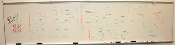
This analog drum machine project synthesizes a kick and snare drum that are clocked to a beat. It pulls together a few analog circuits to do the timing and synthesis.
The beat timing is a product of a hysteretic oscillator used to create a ‘shark wave,’ which is a friendly term for the output of a relaxation oscillator. This waveform can be compared to a set point using a comparator to create a slow square wave that clocks the drum beat.
The kick drum is synthesized using another hysteretic oscillator, but at a higher frequency, creating a triangle-like waveform at 265 Hz that provides a bass sound. The snare, however, uses white noise provided by a BJT’s P-N junction, which is reverse biased and then amplified. You can spot this transistor because its collector is not connected.
The resulting snare and kick drum wave forms are gated by two transistors into the output. Controlling these gates allows the user to create a drum beat. After the break, check out a video walk-through and a demo of the build.


i can’t really see what’s on the white board
What the heck is modcon? (warning, don’t do a google image search for the term)
“After the break”.
:)
Ba da dum tsss…
Why does clicking the picture 1) not give a bigger picture 2) not link to anything useful ?
Keep clicking the picture ’til you can’t click it anymore. I got to a larger picture after about 3 clicks.
Sharkwaves FTW!
With fricken laser beams.
http://www.drumbuddy.com/
infinitely cooler
Excellent video, and a really cool project.
Some quirks: one of the opamp is left with floating non inverting input with respect to DC, the two output BJT are connected in a way so that the output opamps will likely be overloaded by the speaker current draw, especially if the R and D pairs at the transistors emitters are shorted as they’re drawn.