The miniature Christmas village is a tradition in many families — a tiny idyllic world filled happy people, shops, and of course, snow. It’s common to see various miniature buildings for sale around the holidays just for this purpose, and since LEDs are small and cheap, they’ll almost always have some switch on the bottom to light up the windows.
This year, [Braden Sunwold] and his wife started their own village with an eye towards making it a family tradition. But to his surprise, the scale lamp posts they bought to dot along their snowy main street were hollow and didn’t actually light up. Seeing it was up to him to save Christmas, [Braden] got to work adding LEDs to the otherwise inert lamps.
 Now in a pinch, this project could have been done with nothing more than some coin cells and a suitably sized LED. But seeing as the lamp posts were clearly designed in the Victorian style, [Braden] felt they should softly flicker to mimic a burning gas flame. Blinking would be way too harsh, and in his own words, look more like a Halloween decoration.
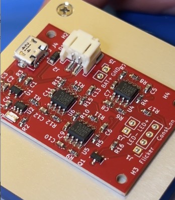
This could have been an excuse to drag out a microcontroller. But instead, [Braden] did as any good little Hackaday reader should do, and called on Old Saint 555 to save Christmas. After doing some research, he determined that a trio of 555s rigged as relaxation oscillators could be used to produce quasi-random triangle waves. When fed into a transistor controlling the LED, the result would be a random flickering instead of a more aggressive strobe effect. It took a little tweaking of values, but eventually he got it locked down and sent away to have custom PCBs made of the circuit.
With the flicker driver done, the rest of the project was pretty simple. Since the lamp posts were already hollow, feeding the LEDs up into them was easy enough. The electronics went into a 3D printed base, and we particularly liked the magnetic connectors [Braden] used so that the lamps could easily be taken off the base when it was time to pack the village away.
We can’t wait to see what new tricks [Braden] uses to bring the village alive for Christmas 2025. Perhaps the building lighting could do with a bit of automation?
Continue reading “555 Timers Bring Christmas Charm To Miniature Village”


