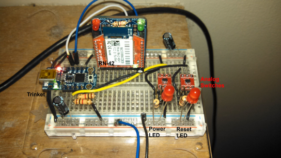
[Mike] wanted to have remote control of the power on his computer. But Wake-on-LAN wasn’t really all that interesting to him. Instead he set out to build this Bluetooth controller which manipulates the motherboard directly (PDF).
Having been a winner of the Trinket Contest he based the project on that board which is seen on the left. There is also an RN-42 Bluetooth module and a couple of TI TS5A3157 analog switches. Once the prototype is finished the entire thing will run off of standby power and be located inside the case of his computer. The breadboard version just switches a couple of LEDs, but that will end up connecting to the pins for the power buttons once installed.
The video after the break shows off the easter egg. The device is controlled by [Mike’s] custom Android app. Every 42nd time he sends a power command the device calls back with our URL.
This is an entry in the Fubarino Contest for a chance at one of the 20 Fubarino SD boards which Microchip has put up as prizes!


Why use analog switches? I realise it’s nice to have solid state switching but their switching side is rated up to +7V (V+max + 0.5V)- I don’t know the ATX standard, but can we be sure that there is less than that flowing through the usual computer case switches?
I’d consider using a mechanical relay (assuming +5VSB can provide enough current, which it more than likely can). Either NO or NC depending on whether we’re overriding the power or reset button.
If I were really para^H^H^H^Hsafety conscious (I am) I’d use an RC monostable to enforce in hardware the minimum time the relay stays in the flipped state – then a 1337 haXXor sending bogus commands to my controller and toggling the power at 20Hz won’t frying everything. See the Belkin WeeMo hack to see what can do wrong.
The PC switches I have seen in several motherboards basically shorts to
ground when pressed. You could use an open collector to drive it. e.g. a
$0.10 transistor in an easy to breadboard package. If you reverse the
connection, it simply won’t turn on without damaging anything. Since
this can be found out easily, using an analog switch buys you nothing.
The problem with the analog switch (V+max + 0.5V) means that there is a
protection diode(s) inside and the part doesn’t like to see the signal
it is switching above its power rail. That can happen when there is no
power on the breadboard (e.g. the wiring got pulled by accident on that
breadboard)? A transistor on the other hand won’t care.
FYI the PC when in “Off” only get power from the +5V_Vstandby from the
PSU. The On/Off switch goes through the motherboard logic to the PSU.
This was more of a proof of concept device. Thanks for the feedback it is very helpful. I did not realize that this could be done simply with a transistor (which makes sense now that I’m thinking about it). I had considered a Mech Relay for this but I wanted to keep the device as small as possible.
I will eventually be adding MAC validation to help prevent haxxor attacks. There is also a timeout function on the MCU which should prevent such attacks. In addition, tekkieneet mentioned that the PC is “Off” when power is only supplied by the 5v_stby (which will be powering this device). I want to add a 5V_sense input on the MCU which should be able to detect this. Would it be safe to directly pass in a 5V power line to the MCU or should I use something like an optoisolator?
Thanks again for all the feedback!
Remember the KISS rule. i.e. Do not bother with optoisolator unless you
really need to have hundreds of volts between two system. I dare any
newbies to tell me that they have designed the circuit to account for
“Current Transfer Ratio” parameter of their optoisolator.
A simple voltage divider (or a 10K series resistor) can easily
provide sufficient protections inside a PC.
What’s the point of letting the software monitoring the standby supply
that you power your project on unless you have a separate supply? That
rail is always on when the PSU is plugged in. If you want to know the
on/off status of the PC, look at the main +5V rail or at the PSU On/Off
control pin.
Thanks for the comment on the isolator. I will try it without it first.
Just to clear up the 5V_sense.. This signal will come from the 5V rail (red wires) of the PSU. This rail is only on when the PC is on. 5V_stby will be used to power the device. I was not entirely clear in the last post.