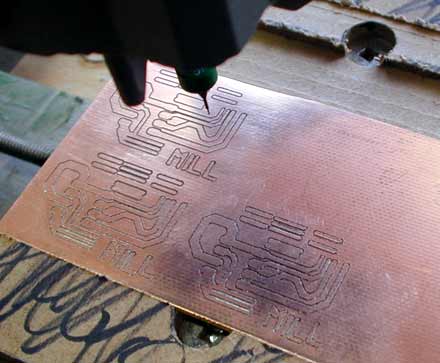
Few Hackaday Readers would disagree with the classic phrase: Necessity is the mother of invention. That statement is certainly no exaggeration when it comes to this mini 3-axis CNC Machine. The builder, [Jonathan], needed a way to prototype circuit boards that he designed. And although he admittedly doesn’t use it as much as he intended, the journey is one of invention and problem solving.
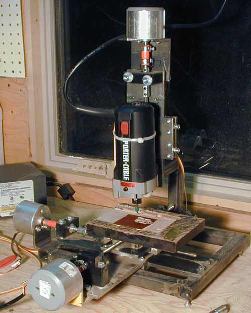
[Jonathan] started from the ground up with his own design. His first machine was a moving gantry style (work piece doesn’t move) and ended up not performing to his expectations. The main problem was alignment of the axis rails. Not becoming discouraged, [Jonathan] started on version 2. This time around the work piece would move in the X and Y directions like a conventional vertical milling machine. The Porter-Cable laminate trimmer would move up and down for the Z axis. It is clear that the frame is built specifically for this project. Although not the prettiest, the frame is completely functional and satisfactorily stiff for what it needs to do.

Each axis is driven by a surplus stepper motor and transmits power via 1/4-20 threaded rod lead screws. Bearings mounted in polypropylene bearing blocks are used to axially locate the lead screws. This is important because the stepper motor bearings are not designed to take axial load. Flexible couplings made from plastic air hose compensate for any mis-alignment between the motor shafts and lead screws.
An entertaining problem (for us readers) was encountered after some time of machine operation. Wood and PCB dust mixed with the grease used to lubricate the axis rails. This combination of materials turned into a glue-like substance making the axes difficult to move. A complete disassembly was required to clean out the gunk. Dry film lubricant proved to be a better choice for this application.
[Jonathan] encountered very common problems that face most CNC machine builders. His solutions were simple and effective and that is what makes this build great.


Very cool! I recently (over the course of the past year) build a 4′ x 4′ gantry style and know the time and energy it takes to build something like this. My question to you: Does that router have a tight enough tolerance to accurately mill traces? A second question: What software ya running? Eagle and LinuxCNC?
Define accurately. Milling printed circuits is never a very good solution really.
When traces are so close ya have to have some tolerances. I’ve read the smaller roto-tools have loosey goosey bearings. I’ve been working on getting my Eagle to output g-code to etch some boards but haven’t made much progress yet.
Have you thought about adding a 3d Print head and make it multi-function?
You could mill toilet seats on this thing, that way you can make some profit out of it.
Dafuq?
Nice! I like cheap skate machines :)
I once used a small plastic tube/hose from an aquarium air pump as NEMA 17 stepper coupler (just like this one uses a hose). And it’s amazing how much torque it can handle! Because I didn’t have end stops I thought maybe the tube could serve as one. But it still broke my z axis when the controller lost its track :)
I use air hose on my steppers too! I’m lucky in that they will slip under enough torque. That’s saved my machine more times than I can remember
Nice work, and a great writeup!
Nice job! Really cool when something like that comes together!
At the bottom of each page on his website this guy has noted when he did the project.
At the bottom of the PCB router page, it says “since 2003”. So either it took him 10 years to do a few weekends worth of work, or this has been sitting stale on the internet since the last decade and HaD is so desparate to publish ANYTHING that they are googling until they find old crumbs like this…