Open source test equipment has to be one of the best gifts open source hardware has given back to the community. Nowhere is this more true than in the case of [Nick’s] Re:Load Pro over on Kickstarter. Unlike resistors or similar dummy loads, an active load will always draw the set amount of current regardless of voltage. Active loads are often used to test power supplies and batteries. Is that 2500 mAh LiPo battery overstating it’s capacity? Can the power supply you just designed handle 2.5A at 12V? Both of these are jobs where active loads would come in handy.
The Re:Load Pro is actually the third version of the Re:Load. [Nick] designed the original Re:Load after becoming frustrated at the lack of a cheap active load for testing a power supply. Plenty of people showed interest in the Re:Load, but they wanted more features. That’s where the Re:Load Pro comes in. More than a straight analog design, the Pro has a Cypress PSOC 4 Arm Cortex M0 processor running the system.
[Nick] and his company, Arachnid Labs, are no strangers to us here at Hackaday. When we last covered [Nick], he was asking the USB Implementers Forum about a low cost Vendor ID option for open source hardware projects. Fittingly, the Re:Load Pro is an open source project. The schematics and source code are available on Github.


I’ve been thinking about USB isolation and it’s not easy… There is just one USB isolation chip available, it’s quite expensive and far from being ideal (speeds only ut to usb 1.1, have to manually set speed,…)
I wonder if it’s possible to build cheap usb isolator using discrete parts like ethernet transformers (for AC signals) conjuncted with optocouplers (for DC signals)…
however re:load does not isolate on USB bus, it isolates at the UART bus level, so whole USB circuitry is isolated and there is no need to isolate USB itself. But it would be usefull to have some cheap trick, to isolate USB directly…
Good question. I presume you’re thinking of the ADuM4160. Its datasheet has a good description of the challenges of isolating USB; the isolator needs to be somewhat stateful to achieve it.
It used to be possible to get separate USB transceivers that split the differential signal into unidirectional, single-ended signals, but as far as I know they don’t really exist any longer. Such signals would certainly be easier to isolate.
For the Re:load Pro, I cheated; there’s an FT230X on the non-isolated side, and the UART serial is what travels over the isolation barrier.
Hey Nick,
I just supported this neat project. I have a few questions looking at the schematic checked into github at the moment. I take it U1 is an isolated power supply to generate +5 for the load side (or it looks like you have an alternative circuit using X1?).
Is there a way to power this device without connecting it to a computer?
Will 5V into the USB w/o enumerating the FT230X enable U1/X1?
If not, could you think about adding a connector and any necessary isolating diodes/fets so we can power the box on our lab bench without a computer?
Good questions!
U1 is indeed an isolated 5v-5v transformer; it’s the RBE-0505S. X1 is the expansion slot.
The FT230XS is configured such that it will enable power to the Re:load when enumerated, or also when plugged into a dedicated charging port – so you don’t need a computer, just a USB power source.
I’ll definitely be modifying the expansion header to include everything necessary to provide an alternative power input.
You can build isolated USB by using Maxim’s USP-SPI chip and isolate the SPI signal with *fast* logic level isolators, add isolated power supply etc. if you want to roll your own protocols instead of USB serial.
Have a look at how Linear Tech does isolation on their Linduino. http://www.linear.com/solutions/linduino . Its a micromodule that not only isolates USB, but provides isolated power too. Doesn’t look like its available for sale separately yet, though.
There are USB isolators(and extenders) that use optic fiber, but they are expensive.
DIY style you can go for either:
-12Mbps only chip
-USB over ethernet, flavors from 100Mbps+USB1 up to 1Gbps + USB3.0.
-USBIP on a router(or something else), but the devices support is rather limited.
Relating to this project…. i’m a bit disappointed.It looks great and I was going to get one, but just constant current? No constant R, no constant P?
He said in the kickstarter that he’s implementing constant P and R, it’s just a matter of writing the code. They will ship with that feature.
(Also sorry, I hit ‘report comment’ instead of ‘reply’ argh)
Constant R doesn’t need FW changes, it needs HW changes, rather simple ones. I am not sure that constant P with software loop will be fast enough….
What hardware changes did you have in mind? With an analog design, you could connect the potentiometer setting the reference voltage for the + terminal of the opamp to the source, but that doesn’t work here: the voltage is generated internally using a DAC.
You can use a fraction of the input voltage as the DAC reference, with the DAC setting you can emulate a potentiometer. But yeah, it is quite limited. I think digital POT might be better suited.
Unfortunately, that’s not really practical here: the DAC is a current DAC, not a voltage DAC. Digital pots are nice, but don’t really come in resolutions higher than 8 bits.
How about a dual pot, like MCP4231, and cascade one after the other. You might be able to get to 10bits or so resolution.
I’m not sure how you could turn two equal-value variable resistors into one higher resolution variable resistor?
Figure 5, but you don’t necessarily need the buffer between them, you can account for the error in software: http://www.analog.com/static/imported-files/application_notes/AN-582.pdf
You basically create a pot that has p = p1 * p2, where p1,p2 are the fractions of the original two pots.
I’m building a power supply with a usb interface, I’m using a usb->serial ttl converter, and isolating at the ttl level.
EASY!
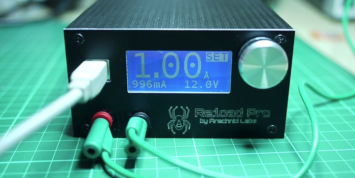
I like the layout and look of the front panel.
Looks like the control loop is in hardware-wonder what kind of response time they get with that. Always prefer a good op-amp on the loop personally
The control loop is an opamp – there’s one built into the PSoC 4.
the price has doubled (damn!) since I bought mine, but this ‘chip’ looks like a simple way to do this task, just add arduino (sorry):
http://www.ebay.com/itm/ELTEST-EL2A-LC-DIGITALLY-PROGRAMMABLE-ELECTRONIC-LOADS-DTL2A-LC-COMPATIBLE-/121302512918
search on eltest el2a or dtl2a.
Well, you can always do it by putting together the pieces resulting in something similar to the project here. You need optocoupler, 12 bit DAC, op-amp, power transistor and passives.
all you need is a fet, an opamp, a pot, and a low value (shunt) resistor to make one … dave jones has a tutorial on it and its soooo much cheaper
Nice module. However if I were to go to the trouble to build my own active load, I’d prefer a discrete load transistor that can be easily replaced if destroyed; rather than replacing a rather expensive module (if replacements are even available).
What are you talking about? There already is a load transistor and it’s a few bucks on usual places.
http://www.findchips.com/search/BTS141
I was replying to [Brian] specifically about the Eltest module he posted, which is $40 and includes some neat features, but is presumably not easily repairable should the load transistor blow.
i own an epic reload … it has its problems but nothing a 10 turn pot, 9v battery and a cheep ebay volt meter cant fix
it uses a 100mv to 1A range … i got a 33v meter and i simply removed the voltage 10x divider and it works wonders!
How will it behave when i setup the load to say 1 Amp and connect it to some signal?
Will the current ramp up or down? I am worrying about current spikes when connecting the load. Is it possible to have the load act as a resistance until the desired current is reached (making it a “current limited resistor”)?
What do you mean by ‘some signal’? You could certainly do that sort of thing in firmware, though it won’t be a stock feature.
I was worrying about current spikes when the load switches from open circuit to normal operation.
For example if you connect the load to a high side switch (FET/Bipolar switch or relay) and the switch changes from OFF state (0V output / high impedance) to ON state.
Using a simple constant current load you will get a high current peak because when the switch is OFF the load acts as a short circuit. When the switch is turned ON the load will regulate the resistance starting from short circuit until the desired current is reached.
It may in some cases be better to increase / ramp up the current as the voltage across the load increases – effectively making the load act as a resistance – until the desired current is reached.
It also depends a lot on the AC (“AC” as in “pulsed DC”) performance and how fast the software can switch from R mode to constant current mode. Are there any specs on accuracy / AC performance etc.?
I’ve put together some very rough scope traces here: http://imgur.com/a/26iRL
They depict the Re:load handling a 500hz waveform switching between 5v and 12v burden voltages at 3A (achieved by shorting a 2 ohm load in series with the Re:load using a FET). As you can see, it takes approximately 80-100 microseconds for the load current to return to normal after the switch turns on or off. In the switch-on phase, there’s a spike in current usage of about 1A that lasts about 20 microseconds.
This is all entirely down to the opamp feedback loop; I don’t think software control for ramp-up is realistic if you want good performance.
A couple of disclaimers: This was tested with my crap benchtop power supply, which doubtless has poor characteristics and high internal capacitance; my scope is a fairly basic Rigol with 50MHz bandwidth.
Is it possible to create a timeline [ms] to define the load as a function of time? Like a little csv file for each line a timestamp and load?
You can control the Re:load Pro over a USB interface with simple text commands, so it would be very easy to write a program that streams instructions to it like this, yes!
Do The cmds have timing information? Or has the windows tool to manage the timing?
No, but that would be fairly straightforward to add to the firmware.
What I could need:
With a resolution of at least 1ms.
two different modes:
Mode A:
Duty Cycle and Periodtime with 2 load-values. E.x. 100mA, 2A, 33%, 3s.
Mode B:
I’m able to download a file which defines:
-resolution of the levels -> dT
-list of load-values, each dT long
Which I’m able to repeat infinite or play once/n-times.
…eventually the load-curves/-files are selectable via the interface on the device, so that not each time I’ve to download it from the computer. (autonomy)
…I could give some support if you want
I built a controllable load based on Jim Williams’ app note, “A Closed-Loop, Wideband, 100A Active Load”, to test the stability of power supplies. It’s surprising what you can find when sweeping the frequency of load current near maximum levels! The current is continuously controlled by a voltage and can vary full-range (0 to 100A) at ~500kHz bandwidth. It works great.
a photo of my PCB:
http://twitpic.com/e1hlhd