[Alan’s] friend came to him with a problem. He loved listening to his scanner, but hated the volume differences between stations. Some transmitters would be very low volume, others would nearly blow his speakers. To solve the problem, [Alan] built up a quick automatic leveling circuit (YouTube link) from parts he had around the lab.
[Alan’s] c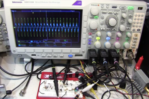 ircuit isn’t new, he states right in the video that various audio limiting, compressing, and automatic gain control circuits have been passed around the internet for years. What he’s brought to the table is his usual flair for explaining the circuits’ operation, with plenty of examples using the oscilloscope. (For those that don’t know, when [Alan] isn’t building circuits for fun, he’s an RF applications engineer at Tektronix).
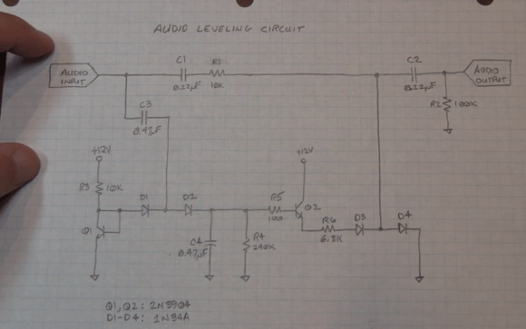
Alan’s circuit is essentially an attenuator. It takes speaker level audio in (exactly what you’d have in a desktop scanner) and outputs a limited signal at about 50mv peak to peak, which is enough to drive an auxiliary amplifier. The attenuator is made up of a resistor and a pair of 1N34A Germanium diodes. The more bias current applied to the diodes, the more they will attenuate the main audio signal. The diode bias current is created by a transistor-based peak detector circuit driven off the main audio signal.
But don’t just take our word for it, watch the video after the break.
Continue reading “Automatic Audio Leveling Circuit Makes Scanning More Fun”


